
The pump industry faces a challenge in keeping up with changing efficiency regulations. Programs such as the Hydraulic Institute (HI) Pump Test Lab Approval (PTLA) are helping companies adhere to these standards. Here, we see how Hydro, Inc. made history with the first HI PTLA certification.
Written by: Michelle Segrest
Publisher: World Pumps / June 2016
With an engineering first approach, Chicago’s Hydro, Inc., proves the impact of redesigned and engineered pumps by testing their real-time hydraulic and mechanical performance at its state-of-the-art Test Lab. It is in the 46,000-square-foot- facility that Hydro develops and implements engineering modifications for improving the performance of critical pumps and then verifies that performance in the lab.
Thanks to high-quality capabilities in testing vertical, horizontal, and submersible pumps, Hydro made history in September 2015 by becoming the first recipient of full certification of the new Hydraulic Institute Pump Test Lab Approval program.
This new industry standard is designed to assist pump OEMs and other pump test laboratories to improve their current laboratory procedures and policies by working with a third-party auditor to develop and maintain accurate, uniform and repeatable pump testing protocols. The program also helps participating organizations adhere to the requirements of the international test laboratory accreditation standard (ISO 17025) concerning test measurement equipment.
“Hydro’s test lab is unique because it was designed to support the aftermarket by having the flexibility to test a wide range and variety of custom engineered pumps,” said George Harris, Hydro CEO and Founder. “Since it is not incorporated in a plant which manufactures new pump production, as is the case with many large OEMs, it is possible to test a customer’s pump in 1-to-3 weeks lead time. This is very important because customers who need a certified test, need the pump tested quickly.”
Since it opened in 2010, Hydro’s 5,000-Horsepower Test Lab has helped to troubleshoot problems with pumps in the field by isolating the pump from its system in a controlled environment to simulate field conditions in a safe manner.
“Hydro remains independent of the constraints that can be imposed by relying on existing hydraulic designs and manufacturers’ predicted performance curves,” said Jeff Johnson, Vice President, Hydro, Inc., a 41-year industry veteran who was instrumental in the design and construction of Hydro’s Test Lab. “All of these efforts ultimately lead to a more reliable and well understood pump performance.”
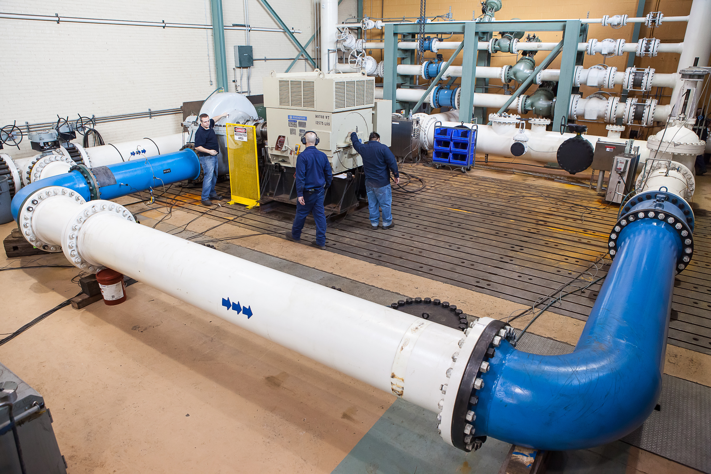
Single-stage horizontal split case (BB1) pump test with customer motor – test loop.