
The phenomenon occurs when a system experiences extreme vibration caused by excessive pump pressure and pulsation.
Written by: Greg Matteson & Jeff Johnson
Published by: Pumps & Systems
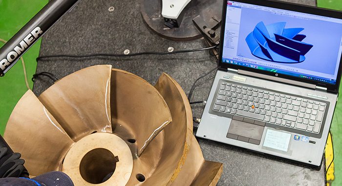
A North American natural gas liquids pipeline company was experiencing an acoustic resonance issue that cost up to $35,000 a month in maintenance and repair. A six-week project resulted in rerating three American Petroleum Institute (API) designation between-bearing (BB3) horizontal multistage split-case mainline pumps and performing extensive and specific vibration analyses to identify the problem. The project involved designing and manufacturing new impellers using exclusive milled vane technology, conducting API hydraulic performance tests, and returning the pumps into service.
This midcontinent pipeline gathers, processes, stores and transports natural gas—in this case, propane. Because of its geographic location, extreme temperatures and conditions are a factor in the selection of major equipment and components. The pumps operate at 2,917 gallons per minute with 2,926 feet at 1,500 horsepower and 3,560 revolutions per minute (rpm).
 The Problem
The pipeline company was experiencing an acoustic resonance vibration problem at the pump crossover, causing major maintenance and repair issues. Acoustic resonance occurs when a system experiences extreme vibration due to excessive pump pressure and pulsation, with frequencies loud enough for humans to hear. This can happen with the use of variable speed drives.
The pulsations are caused by a non-uniform flow from turbulence, sudden change of flow structure, direction or cross-section.
The acoustic resonance had existed since the pumps were installed more than five years ago. Rather than repairing or replacing them, the company performed continuous unscheduled maintenance that cost as much as $35,000 in a single month.