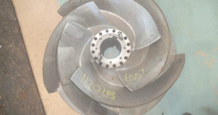
The pump after upgrades and repair now has an impeller that operates at run-out flow condition safely and as per design.
A power station’s cooling water pumps were constantly being repaired, costing the plant millions of dollars in costs and service time due to the severe operational disruption and logistics required to remove and transport such large equipment. Previous attempts made by the station to improve the reliability of the impellers through upgraded material selections had little impact on reliability.
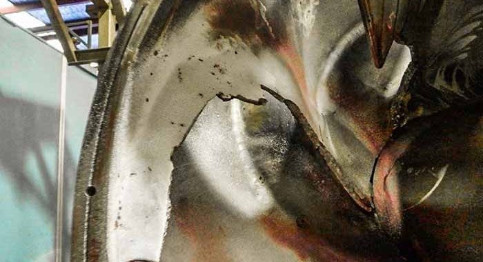
It was clear that something had to change as the station’s pump reliability was now a major financial focus. The many vane cracks, cavitation and broken vane sections that were weld-repaired during inspections throughout the pumps’ life cycles prompted the station to investigate a more permanent solution to the issue.
During the last repair, the reliability engineer inspected the impellers and found the cavitation was similar to those reported during prior repairs. An engineering repair company that specializes in fluid dynamics was asked to investigate the root cause of the continuing pump issues. The team conducted an investigation on the system layout and operation parameters.
The results of the forensic analysis showed that the impeller blades were suffering cavitation to the low-pressure side of the vanes. Additionally, the cavitation and cracked vanes toward the eye also indicated that the sizing of the inlet and its associated blade angles may be active factors in the repeated failures.
Source: https://www.pumpsandsystems.com/engineered-battle-against-cavitation


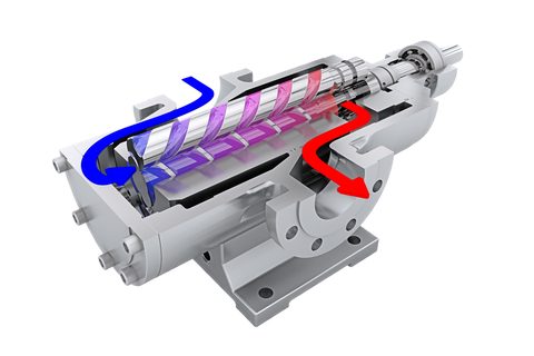 Two trusted names in the industry have formed a powerful partnership for supporting diesel fuel and lube oil pumps.