Power pump performance improved with redesign of the first-stage, double-suction impeller and twin volute.
This project has been divided into two articles. The first, published in the June 2017 Pumps & Systems; the second, published in September 2017 Pumps & Systems.
Written by: Dave Allard & Dr. Gary Dyson
Published by: Pumps & Systems
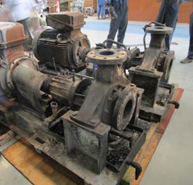
In the aftermarket business, part replication is not enough. Precision engineering combined with the latest technology are essential for manufacturing high-quality parts. A main boiler feed pump at a Midwestern United States power plant was built in 1967 using sand casting and wooden patterns, now considered outdated technology. Even though the pumps received refurbishment every six to eight years, the pumps continued to have low performance as well as vibration issues.
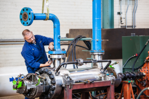
Using all its resources—including casting simulations, 3-D models, up-to-date foundry casting techniques and considerable engineering data—Hydro fully manufactured a complete element, performed sophisticated testing in the Pumps Test Lab Approved Program (PTLA) certified test lab, and returned the pump to operation within just 12 weeks.
This project involved the manufacture of a complete first stage twin volute and a description of the latent defects.
The pump suffered from ongoing vibration issues which were caused by pressure pulsations at vane frequency. To improve the vibration levels, hydraulic analysis and redesign were required to develop a new, improved design.
This project has been divided into two articles. The first is the manufacturing of the twin volute and the second is the design of a new impeller.
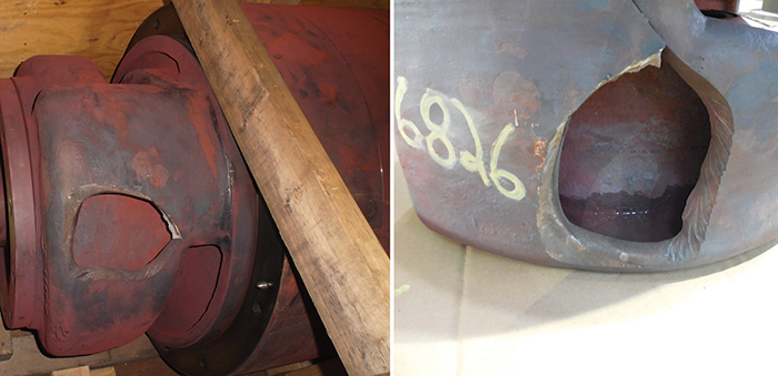
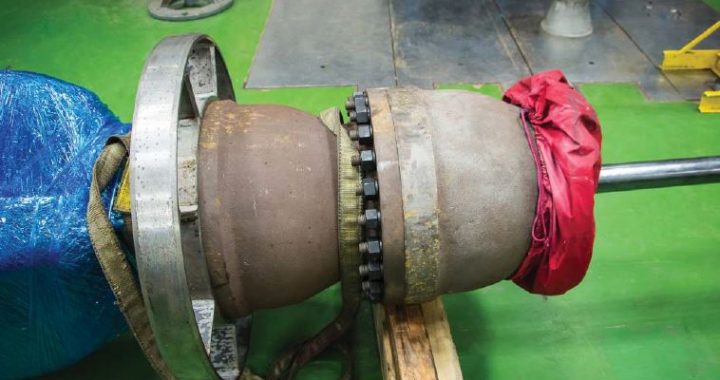
Image 1. A received bundle showing failure in the twin volute stage piece. Hydro received the internal element and casing (pump bundle, or element) of the pump. (Images and graphics courtesy of Hydro, Inc.)
The first-stage twin volute is a complicated casting, which failed during operation as a result of poor design.
Hydro re-engineered the casting by using sophisticated engineering and 3-D modeling, along with simulation software and 3-D sand printing.
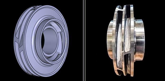
In addition, Hydro identified the opportunity to improve the performance of the pump by redesigning the first-stage double-suction impeller. To improve vane passing frequency, the first-stage double suction impeller was redesigned with staggered and split vanes.
Hydro’s aftermarket services capability provided a completely new replacement element for this high-energy boiler feed pump and also redesigned the castings to eliminate the original latent defect in the casting design.
Hydro provided sophisticated hydraulic engineering improvements to increase the mean time between repairs (MTBR) of the newly manufactured element.