Impeller Failure Solution at a Vietnamese Power Plant

Written by: Kwa Soo Teck, Phu My 3 Power Station (Vietnam), & Chandra Verma, Hydro Australia
Publisher: Pumps & Systems / September, 2011


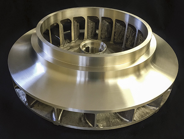
Phu My 3 BOT Power Station, a Vietnamese power station using combined cycle gas turbine technology and operating at 749 megawatt capacity, had been experiencing some problems with their vertical pumps. The station asked Hydro Australia to assess the damage and assist with a solution.


The power plant in Vietnam


The vertical pumps were used for the circulating water system. The impeller material was a super duplex and the product being pumped was sea water. Over a period of three years, Phu My 3 had experienced catastrophic failures with the impellers and were unsure of the cause. The first pump was installed in Sept 2003 and the first blade failed in September 2008; the second failure occurred in Sept 2009 and a third failure occurred in June 2010.

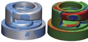
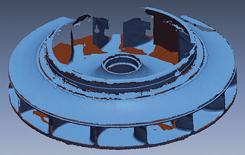
On viewing the damaged impellers, which weigh 850 kilograms, it was obvious the quality was poor. The first step in the process was to send over an engineer with a Romer Arm, a 3D coordinate measuring instrument, to reverse engineer the impeller. This data could be used to analyse the existing impeller design.


Continue reading

Performance Testing for a Rebuilt Pump

Written by: Jeff Johnson, Hydro, and Bill Rademacher, BP

Publisher: Pumps & Systems / April, 2011


A refinery’s vertical pump passes the test, verifying its performance before installation.

The rotating equipment engineers at BP’s Whiting Refinery in Indiana approached the support team at a pump service center in Chicago to discuss testing its rebuilt vertical turbine pump in the center’s new 5,000-horsepower test lab. Their pump, a Johnston 40 GMC pump, is one of four pumps used for the refinery’s rainwater drainage and process sewer system. This pump is the first pump in line and has a diffuser built onto the suction bell to direct flow into the pump.

Two other pumps are in line behind this pump and a fourth pump is to the side. All are mounted in a large concrete channel system. BP had implemented a specially designed suction strainer on this pump to minimize potential sump vortexes from entering the pump through the suction side of the impeller.


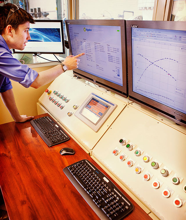
Hydro’s 5000 HP Test Lab in Chicago, IL


This vertical pump had been rebuilt and modified by trimming the impeller and opening the inlet diameter (ID) of the suction bell to improve the flow path characteristics into the impeller eye opening. The refinery wanted verification that the modifications made to the pump resulted in the calculated decreases in horsepower and NPSH required. The goal of the tests, as defined by the refinery, was to determine the operating characteristics, including head (total discharge head—TDH), flow and horsepower, as well as the minimum submergence level of the pump so it could adjust its operating set points and submergence level alarms to avoid cavitation damage.

As the pump service center maintains an “open door” policy, several individuals from the refinery visited the test lab over a two-day period to observe the testing process, which proved to be an educational experience.


Johnston 40 GMC vertical pump on the test stand


The Performance Test

Because BP provided the 1,000-horsepower pump motor, the service center engineers were able to set up both the vertical pump and the motor in the test lab. Using this set-up, the service center engineers would be able to help BP obtain an accurate understanding of how their pump would perform in the field.

The service center engineers conducted the performance test and used a validation program to calculate the efficiency using data inputs such as flow, horsepower, barometric pressure, suction level, discharge pressure, temperature and specific gravity of the water, diameters of the piping system and the location of discharge collection points.

The pump’s best efficiency point (BEP) was proved at just under 18,000 gallons per minute, at about 130 feet of head, using about 750 horsepower. Proving the BEP of its pump will enable BP to determine how it should operate the pump most efficiently in the field.


The Minimum Submergence Level

The service center engineers performed a submergence test to show BP where its low sump levels should be set. Cavitation was anticipated at a depth of 39 inches and the service center engineers were able to show the pump’s performance at its lowest submergence point before cavitation could occur, which was 42 inches. The minimum submergence levels were proved so that BP could ensure the best level settings could be achieved in the field without causing damage to the pump.

Ironically, the test pool turned out to be a close replication of the refinery’s sump. This enabled the service center engineers to confirm BP’s suction strainer had been effectively designed. The witnesses to the test could visually see how the suction strainer sheared vortexes that had developed in the sump at low submergence levels.

Continue reading

Repair and Renewal Offer Fast Turnaround and Cost Savings

Written by: Ron White & Ben Roberson, HydroAire Inc.

Publisher: Pumps & Systems / February, 2011


A “temporary” repair results in five years of service.

Five years ago, an engineered pump service center in the Midwest received a call from a large municipal sanitary district. One of the company’s four submersible pumps had tripped the overloads. This 890-rpm unit operated on variable frequency drives that adjusted the motor speed to match the fluid inflow. Once it had been reset, the 290-horsepower, 42-inch diameter axial flow pump exhibited significant vibration before failing. The pump was removed and sent to the service center where it was cleaned, disassembled and inspected by a team of skilled professionals dedicated to repairing submersible pumps.


Figure 1. 290-horsepower submersible pump upon arrival at the service center


The Assessment

The initial inspection revealed that a large chunk of concrete debris from nearby sewer construction caused the submersible pump to fail. The inspection also showed that the pump had several problems:

  • A section of the trailing edge of one of the impeller vanes was broken.
  • The rotating ring was missing.
  • The impeller hub and lower mechanical seal had cracked and caused damage to the shaft keyway.


Figure 2. The cracked impeller hub


When the municipality inquired about replacement parts from the OEM, delivery was estimated at a 12- to 14-week turnaround time on a new impeller from Europe. The municipality could not afford to be without the pump for an extended period of time. Having a great deal of experience with submersible pumps, the dedicated submersible repair division proposed a temporary solution to get the pump repaired and back into service until the municipality could obtain a new impeller from the OEM.


Continue reading

Reverse Engineering–an Alternative to Traditional Pump Repair

Author:

George Harris, Hydro Inc. & Dibu Chowdhury, HydroAire Inc.

Publisher:

Pumps & Systems

Date Published:

November, 2010


With reverse engineering, a pump service facility increased the performance of a service water pump in a nuclear power plant.

When an East Coast nuclear plant wanted to increase the performance of its Layne & Bowler 25 RKCH two-stage vertical lineshaft, wet pit, service water pump, reverse engineering services to upgrade the repair of this unit was chosen. Driven by a 350-horsepower, 1,200 rpm vertical motor, this unit is approximately 45 feet in suspended length. This pump is considered a low suction energy unit with about 3,500 specific speed.


Reverse Engineering: a Proven Alternative

Pump components requiring reverse engineering are rarely new items. They may have deteriorated through in-service use or have been damaged by cavitation or pump failure. Reverse engineering has become a proven alternative for obtaining replacement parts for existing equipment. Replacing these parts requires experienced design and processes to create a component that will meet the form, fit and function of the original part.

Using a portable, coordinate measuring machine (CMM), in conjunction with specialized computer-aided design (CAD) and 3D software, an initial vane layout was prepared using the existing blade.

When reverse engineering hydraulic components, ensuring that the new component will be equivalent to and meet or exceed all the specifications of the original design is critical. In this example, reverse engineering was used, along with the portable CMM, to develop the new castings. In a vertical pump bowl assembly (as in this unit), this is challenging due to the need to interface hydraulics between the vane lay outs of the impeller and the bowl diffuser.

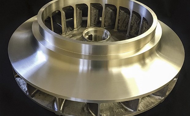
This process requires in-house vane layout hydraulic technology, which may be necessary to re-engineer the deteriorated impeller and diffuser vanes. CAD software was used to overlay the new vane geometry on top of the original blade to ensure that an equivalent component was produced. The hydraulic passageways were polished to increase pump performance.


New, reverse engineered hydraulic component


Reverse engineering with assistance of the portable CMM


Continue reading

When Maintenance of a Condensate Pump Becomes an Emergency

Author:

Dr. T. Ravisundar, HydroAire Inc.

Publisher:

Pumps & Systems

Date Published:

September, 2010


In this case study, routine maintenance of a condensate pump at a nuclear power plant becomes an emergency situation.

When a nuclear power plant pulled its vertical condensate pump for routine maintenance, an emergency situation was not expected. The plant pulled the pump and installed a replacement from storage, but it failed catastrophically after only two days in service.

Requiring a solution for the emergency need, the plant accepted a workscope from a service center that promised a refurbished pump within nine days. The plant shipped both pumps to the service center and sent a condensate system engineer to oversee the work and maintain an open line of communication between the organizations.

This case study highlights the root cause of pump failure for a nuclear power plant and the emergency response required to repair the pump.


Teamwork Critical to Quick Turnaround

One key factor to successfully handling this emergency pump failure was the close teamwork between the plant’s management, an onsite plant engineer located at the repair facility and the personnel at the repair facility. A lesson learned for pump users in emergency situations is that close teamwork and having a customer engineer onsite is critical to facilitating a rapid response.


Root Cause of Failure

The pump failed as a result of having been previously incorrectly repaired, coupled with contributing installation issues, ultimately causing the upper shaft to break. Evidence of the root cause became apparent during the disassembly process. These photos illustrate what the pump service center found.

Ductile Fatigue Failure: The head shaft cracked at the snap ring groove just before the last stage impeller front hub ring turn.

Best practice is to maintain stringent alignment and concentricity between interfacing parts. This ensures correct concentricity and perpendicularity between shaft and bearings and rotor to casing. The service center discovered that the top bowl male fit had been previously repaired by pad welding (see Figure 1), which is an improper practice due to the presence of a sealing O-ring. When a pad weld is performed on a pump that uses the O-ring design, fits and tolerances no longer meet acceptance criteria. It appears that the previous repair provider coated the faces with silicone or another sealant in an attempt to re-establish the proper fits or control leakage (see Figure 2).


Figure 1. Pad welded male fit for the top bowl.


Figure 2. Silicone coating appears to have been used in a previous repair after the male fits were pad welded in an attempt to seal the proper fit between the top bowl and the discharge head.

Continue reading