A US fertilizer plant was experiencing recurring reliability problems with its horizontal multistage boiler feed pumps. The series of repeat failures motivated the owner plant to consult with a widely-known unbiased aftermarket pump service provider. Previous experience with this company’s Texas facility gave the plant confidence that they had the capability to troubleshoot the problem and provide a solution. This type of supplier has been classified as a “CPRS”— Competent Pump Repair Shop, because their worldwide affiliates are staffed by specialists who have the fullest support of pump engineers at the company headquarters.
The aftermarket pump service provider performed a failure modes and effects analysis (FMEA) that took into consideration historical failure information and included an independent engineering analysis of the operating conditions. A review of the system history uncovered that the fertilizer plant had originally been designed with two 100% pumps. When the system was uprated, increased output requirements necessitated that both pumps operate in parallel to meet the new demand. Based on this information, the FMEA determined that the most probable failure mechanism was discharge recirculation caused by low flow operation.
The aftermarket pump service provider and the plant agreed to complete disassembly and inspection on the next degraded pump to validate the probable root cause. As expected, recirculation damage on the impellers and casing confirmed the analysis. Upon mutual agreement of the failure mechanism, the service center’s engineering team recommended a modification to the impellers to once again allow the plant to meet the system demand using one pump. The impeller modification moved pump operation away from the problematic low flow range and ensured future reliability; this modification also provided other significant benefits to the plant.
Parallel Pump Operation and Its Drawbacks
Many fertilizer plants have increased their output from the facility’s original design, requiring increased process flow. In some instances, the original pump design will have enough head and NPSHr margin to meet the new required flow. However, it is more often the case that the other installed pump must be brought into operation in parallel to meet the new required flow rate or to compensate for future wear.
Unfortunately, changing from a one-pump operation to a two-pump operation causes each pump to operate much closer to unacceptably low flow. As a pump operates further to the left of the best efficiency point (BEP), significant problems related to higher loads and hydraulic instability begin to arise. Considerable detrimental effects occur when the pump does not operate within the range of 80% to 110% of its BEP, as shown in Figure 1. The operation of both pumps in a parallel forced each to operate significantly below the acceptable range.

Figure 1: Weibull Reliability Curve- Factors Affecting Reliability Relative to BEP
A centrifugal pump will always operate at the intersection of the total pump curve and the system resistance curve (Figure 2). For pumps running in parallel, the combined pump performance curve is created by adding the individual pump flows at the same total developed head (Figure 3). Each individual pump will operate where the combined pump curve intersects the system curve (Figure 4).
The following example shows how adding a pump in parallel to meet an increased system demand can cause each individual pump to operate at low flow. Suppose that a plant had a pump originally designed to deliver 1,000 gpm. Changing conditions now require 1,200 gpm from the system, which the single pump is unable to deliver. Operating two pumps in parallel requires 600 gpm from each pump to make up the 1,200 gpm total requirement. In this condition, each pump is operating at 60% of its original design operating point and in a flatter portion of the curve.

Figure 2: Single Pump Operation. In a single pump system, the pump will operate where the pump performance curve intersects the system resistance curve.

Figure 3: Developing Total Pump Curve. To get the total pump curve for parallel pumps, add the flows for each pump at the same total developed head.

Figure 4: Determining Single Pump Operating Point in Multiple Pump System. In a multiple pump system, the pump head will be determined by where the total pump curve intersects the system resistance curve. Each individual pump flow is the flow rate that coincides.
Pumps are designed to operate at or near their best efficiency point (BEP) in the steep region of their unique performance curve. Operating back on the curve where there is less head rise can lead to uneven load sharing, resulting in pump surging and other detrimental effects.
Two factors that aggravate this undesirable condition are:
- Different wear rates and refurbishment schedules create a “stronger” and “weaker” pump
- At 50-80% of the pump BEP, pressure drops associated with discharge recirculation create a localized flattening of the performance curve
When uneven load sharing occurs between the two pumps, the weaker pump is forced to operate even further back on its performance curve. As shown in Figure 5, the flattening of the performance curve in the 50-80% operating range can worsen this divergence.

Figure 5: Uneven Load Sharing. In a single pump system, the pump will operate where the pump performance curve intersects the system resistance curve.
Inspection and Solution Development
When the subject boiler feed pump was brought to the aftermarket service provider, a thorough inspection was provided to ascertain the root cause of the repeated failures. Inspection revealed evidence of recirculation both on the impellers and on the casing volutes.
Recirculation damage is highly indicative of operation away from the pump best efficiency point. At the BEP, the angle of the flow matches the angle of the stationary impeller blades and volute cutwaters. As pump operation diverges from the best efficiency flow, the angle of the flow and the blade angle are no longer compatible and the likelihood for fluid recirculation increases. The recirculated flow will cause component damage, localized pressure drops, and decreased rotor stability, resulting in degraded performance and high vibration.
While there are many ways to try and counteract the detrimental effects of fluid recirculation, the best solution is to move operation as close to the best efficiency point as possible. The aftermarket service provider’s engineering team reviewed the pump performance data and the system requirements to understand how best to move the pumps away from the low flow condition back to a safe operating regime.

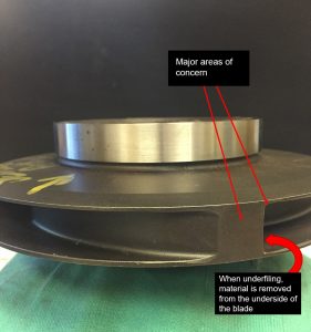
Figure 6: Areas of Concern – Underfile
The site was presented with two options: manufacture rerated impellers to optimize the pump for the system or underfile the existing impellers to provide more flow. Both of these options would return the site to operating with one 100% pump instead of requiring operation with both installed units.
The first option presented to the site was rerating the impellers for the new duty point. Through the extensive capabilities in their company network, the Texas service center had access to capable pump engineers, computational fluid dynamics experts, and a certified pump test lab to ensure that the rerated design would successfully meet the required operation. In fact, rerating the impellers would likely provide better performance and efficiency than the site had ever achieved. This is because the hydraulics would be completely customized for the operating point rather than selected as a “best fit” from pre-established impeller models as occurs during the original OEM design.
While a hydraulic rerate would allow greater flexibility for future operation changes, the site was concerned about the risk presented by not having a spare onsite for the amount of time necessary to cast and machine new impellers. As such, the customer decided to underfile the existing impellers. When an impeller is underfiled, the material is taken away from the underside of the blade at the impeller outlet to increase the impeller passage size. This provides more flow at the same total developed head.

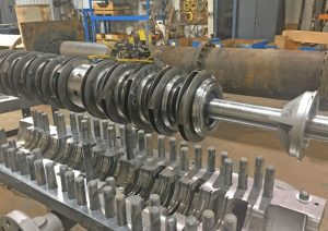
Figure 7: Rotor with Underfiled Impellers
While it sounds like a simple process, there is a lot of engineering required to successfully complete an underfile modification. A study must be undertaken to determine the appropriate amount to underfile the blade to achieve the required performance. Careful consideration must be made to how much material is removed, as this is a highly stressed area and excessive material loss can weaken the impeller and greatly increase the risk of component failure. Providing the proper geometry where the impeller blade meets the shrouds is also important to minimize the stress concentration factor in this area.
The service center completed the underfile modification and remediated the recirculation damage on the impellers and casing. As is typical for this service center, a full dimensional analysis was performed and measures were taken to ensure the optimal fit-ups and tolerances for reliable operation of this high energy, multistage pump.

Figure 8: Underfiled Rotor and Refurbished Case
Collateral Benefits
When the modified pump was reinstalled and returned to service, the plant was able to meet the system requirements and achieve smooth operation with one pump.
In addition to expecting significantly improved reliability, changing the pump performance to provide single pump operation has provided substantial collateral benefits. Only requiring the operation of one pump to meet system needs allows the site to have an installed spare. In the event of a catastrophic failure, this will eliminate the downtime associated with removing the failed pump and installing the spare element.
Another benefit of optimizing pump operation for the single pump is a reduction in the horsepower required to provide the system flow. This optimization fits into the drive to improve energy efficiency and reduce the overall cost of operating the plant. As shown in Figure 10, operating a single pump at optimal efficiency instead of two pumps at a lower efficiency will save the site an estimated $69,000 annually.

Figure 9: Estimated Horsepower Savings
Moving forward, the plant intends to modify the other pumps to better match the system. Because future pumps will be refurbished as planned maintenance instead of a quick turnaround repair, consideration is being made to upgrade the other pumps to the rerated impellers. This modification will give the plant even greater flexibility so that, in the event that system flow rates increase again, the single pump will have enough margin to operate at the higher flow.
Source: https://www.worldfertilizer.com
