The Dangers of Operating Pumps at Low Capacity


Operating at low flow places the machine under a great amount of duress. It is always wise to have a mental picture of what is happening within the passages of the machine to understand why this is the case.

The days have long passed where pump vibrations were viewed as a matter of mechanical balance. Now, we recognize that even if the pump had perfect mechanical balance, it would still exhibit vibrations.

The intensity of this remnant vibration turns out to be flow related with its minimum level being at or around best efficiency point (BEP).

Source: https://www.pumpsandsystems.com/dangers-operating-pumps-low-capacity

Wear in Centrifugal Pumps

Illustration of wear at the volute lip.

Centrifugal pumps are sometimes used in environments where the pumped product contains suspended solids. While some pumps are specifically designed for solid handling or slurry applications, normal centrifugal pumps do not contain features to prevent performance degradation from the impact of solids.

There are a few key signs that a conventional centrifugal pump is suffering from erosive and abrasive wear. Here are assessment and mitigation strategies to be considered and applied when this occurs.

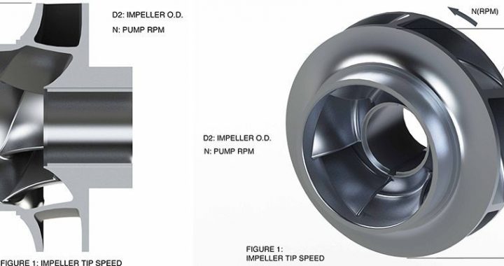
Particles are a problem in a centrifugal pump due to the way the machine adds velocity to the liquid as it passes up the impeller channels. In general, the higher the speed at the tip of the impeller, the more energy that is imparted to any particle that is suspended within the liquid. This energy can then cause damage to anything it impacts.

Source: https://www.pumpsandsystems.com/wear-centrifugal-pumps 

Engineering a Long-Term Solution

Figure 1. The pump as received

Many pumps in operation today were designed and manufactured decades ago. As plants require increased capacity, pump systems are expected to meet these higher process flow demands. Without an impeller rerate or change in speed, this increased capacity can be achieved in one of two ways. The individual pumps can supply more flow to the system, resulting in operation out on the pump curve. Alternatively, capacity can be increased by operating more pumps in parallel; in this case operation is pushed back on the curve, as operating another pump in parallel requires less flow from each individual pump to meet total system demand.

Either operational change results in a move away from the pump best efficiency point (BEP). As a result, the original designs and hydraulic characteristics no longer effectively meet plant requirements and detrimental effects from hydraulic instability can occur.

By way of example, this article will discuss a fertilizer plant in the Gulf of Mexico that had a boiler feedwater pump unit that was experiencing performance problems after a significant plant expansion project. Unfortunately, it was not the first time this particular unit had experienced a loss of capacity; the pump had been in operation only 18 months prior to the current issue.


Increasing MTBR Under Emergency Conditions

increasing mtbr under emergency conidtionsAs the nuclear industry continues to adapt to new requirements under the Nuclear Promise, it is of key importance for utilities to strengthen existing safety protocols and execute efficiency improvements in day-to-day operations and maintenance to optimize overall costs.

One such nuclear plant found themselves  struggling in regards to a planned outage of a vertical service water pump, providing cooling water to safety-related heat exchangers in the power generation process. In this case, the operating pump was actively exhibiting performance issues and was reaching the end of its lifecycle, requiring their reserve unit be placed into service under expedited conditions.

The principle goal for the plant was increasing Mean Time Before Repair (MTBR) of their pump system to optimize efficiency and reduce costs. Unfortunately, upon initial review of the reserve unit, it was identified that it had a history of poor performance issues under previous use.

Authored by Faisal Salman.
Source: nuclearplantjournal.com

The Basics of Reciprocating vs. Centrifugal Pumps

Image 1. A reciprocating pump’s fixed volume. Flow is determined by stroke, area and speed. (Images courtesy of Hydro)

Understanding the differences between these types of pumps can mean avoiding difficulties and reliability problems.

The demand for the duties that fall within the performance range of reciprocating pumps is rising. Process flows are falling while the pressures required are increasing.

Engineers are generally familiar with operating principles, performance curves and selection criteria for centrifugal pumps, but the training and knowledge around the operating principles of reciprocating pumps is not as common.

Unlike centrifugal pumps, reciprocating pumps have a stronger interaction with the system within which they sit. This is due to the pressure pulsations they generate.

If we think about any linear reciprocating motion of a piston, at some point the velocity of the piston is zero as it changes direction at the top and bottom of its stroke. This means that the pressure pulsations are much larger in a reciprocating machine than in a centrifugal machine.

Authored by Gary Dyson.
Source: pumpsandsystems.com