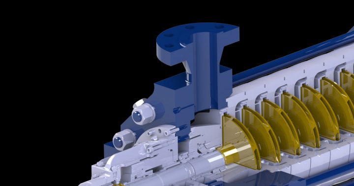
HydroTex Dynamics was founded in 1979 to meet a growing need for aftermarket service in the Houston area. By focusing on quality workmanship and cultivating strong relationships with customers, HydroTex Dynamics has become recognized as a premiere service location not only in the Houston area, but across the US. As an independent, they have expertise across OEMs and applications, with a strong focus on the power market and high-energy multistage pumps. The experience base and library of upgrades they have built support customers in increasing the reliability and life of critical equipment.
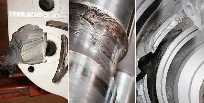
 One of the key milestones in HydroTex Dynamics’ development was the time spent with Dr. Elemer Makay in the late 1980s and early 1990s perfecting the radial gap modifications (commonly known as A Gap, B Gap, and C Gap) on multistage diffuser-style pumps. Dr. Makay was a pioneer in battling impact loading and discharge recirculation in multistage pumps, failure modes that had historically caused high vibration, premature wear, and shaft failures for this equipment. He partnered with Jim Shaffer, founding partner of HydroTex Dynamics, in applying modifications that would combat these failure modes to drastically improve mean-time-between-repairs.
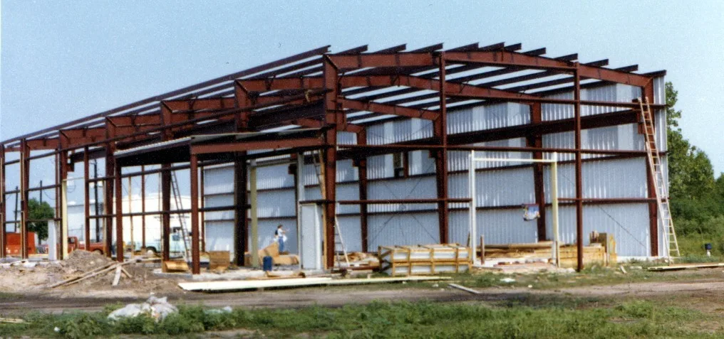
The radial gap modifications were applied to high energy boiler feed pumps across several Texas utilities with great success and are now regarded as a standard design for new boiler feed pumps. HydroTex Dynamics’ experience working with Dr. Makay on this modification provided them not only with an important understanding of factors that affect pump reliability, it also inspired a culture that paid attention to the many small details that add up to a smoothly running piece of equipment. This understanding has driven the service center’s high standards, including strict tolerances for critical geometries and balance, best-in-class assembly procedures, including a pit for assembling multi-stage pumps vertically, and an in-depth dimensional analysis that is the crucial first step in establishing axial centerline compatibility of every impeller within its respective diffuser.
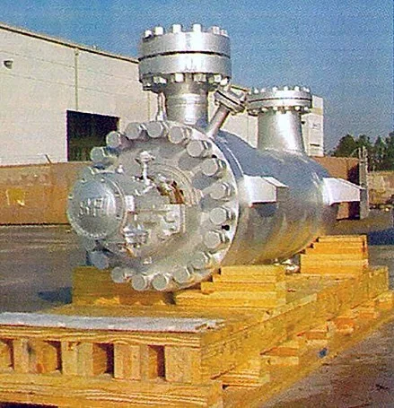 Under the leadership of HydroTex Dynamics’ VP, Pete Erickson, they have continued to build upon this foundation by investing in advanced tooling, developing experienced shop talent, establishing a responsive field service unit, and fostering deep customer relationships grounded in trust and transparency. In 1995, they purchased the Pacific BFI line of BB5 pumps for North America, adding to their experience base in high energy, multistage pumps. They have on-site capability to perform 5-axis machining and can supply milled vane impellers with an industry leading turnaround time. While not currently certified, they are ISO compliant and follow all ISO practices.
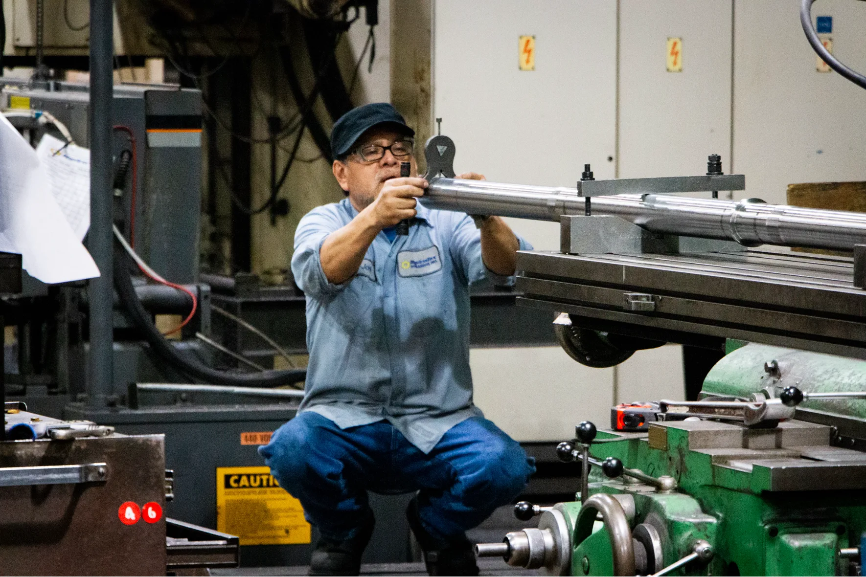
One of the greatest strengths of HydroTex Dynamics is its people. The majority of workers in the shop have been with HydroTex between 15 and 30 years. Their hard-won experience and commitment to excellence is a cornerstone of the superior reputation that the shop has earned. By prioritizing communication and understanding each customer’s needs, HydroTex Dynamics delivers on their promise to provide one source of total support to pump users.
Contact us to learn more about HydroTex Dynamics or explore our global network.


 One of the key milestones in HydroTex Dynamics’ development was the time spent with Dr. Elemer Makay in the late 1980s and early 1990s perfecting the radial gap modifications (commonly known as A Gap, B Gap, and C Gap) on multistage diffuser-style pumps. Dr. Makay was a pioneer in battling impact loading and discharge recirculation in multistage pumps, failure modes that had historically caused high vibration, premature wear, and shaft failures for this equipment. He partnered with Jim Shaffer, founding partner of HydroTex Dynamics, in applying modifications that would combat these failure modes to drastically improve mean-time-between-repairs.
 Under the leadership of HydroTex Dynamics’ VP, Pete Erickson, they have continued to build upon this foundation by investing in advanced tooling, developing experienced shop talent, establishing a responsive field service unit, and fostering deep customer relationships grounded in trust and transparency. In 1995, they purchased the Pacific BFI line of BB5 pumps for North America, adding to their experience base in high energy, multistage pumps. They have on-site capability to perform 5-axis machining and can supply milled vane impellers with an industry leading turnaround time. While not currently certified, they are ISO compliant and follow all ISO practices.
