Power pump performance improved with redesign of the first-stage, double-suction impeller and twin volute.
This project has been divided into two articles. The first, published in the June 2017 Pumps & Systems; the second, published in September 2017 Pumps & Systems.
Written by: Dave Allard & Dr. Gary Dyson
Published by: Pumps & Systems
In the aftermarket business, part replication is not enough. Precision engineering combined with the latest technology are essential for manufacturing high-quality parts. A main boiler feed pump at a Midwestern United States power plant was built in 1967 using sand casting and wooden patterns, now considered outdated technology. Even though the pumps received refurbishment every six to eight years, the pumps continued to have low performance as well as vibration issues.
Using all its resources—including casting simulations, 3-D models, up-to-date foundry casting techniques and considerable engineering data—Hydro fully manufactured a complete element, performed sophisticated testing in the Pumps Test Lab Approved Program (PTLA) certified test lab, and returned the pump to operation within just 12 weeks.
This project involved the manufacture of a complete first stage twin volute and a description of the latent defects.
The pump suffered from ongoing vibration issues which were caused by pressure pulsations at vane frequency. To improve the vibration levels, hydraulic analysis and redesign were required to develop a new, improved design.
This project has been divided into two articles. The first is the manufacturing of the twin volute and the second is the design of a new impeller.
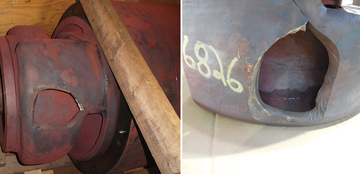
Image 1. A received bundle showing failure in the twin volute stage piece. Hydro received the internal element and casing (pump bundle, or element) of the pump. (Images and graphics courtesy of Hydro, Inc.)
The first-stage twin volute is a complicated casting, which failed during operation as a result of poor design.
Hydro re-engineered the casting by using sophisticated engineering and 3-D modeling, along with simulation software and 3-D sand printing.
In addition, Hydro identified the opportunity to improve the performance of the pump by redesigning the first-stage double-suction impeller. To improve vane passing frequency, the first-stage double suction impeller was redesigned with staggered and split vanes.
Hydro’s aftermarket services capability provided a completely new replacement element for this high-energy boiler feed pump and also redesigned the castings to eliminate the original latent defect in the casting design.
Hydro provided sophisticated hydraulic engineering improvements to increase the mean time between repairs (MTBR) of the newly manufactured element.
Background
The end user came experienced an issue when the life expectancy of a pump case was not meeting expectations. The pump was removed from service due to performance deterioration manifested by increased vibration. The first-stage double suction volute had failed. A crack had developed on the volute initiating from the interface between a welded core plug and the volute casting.
At the foundry, images were taken with an articulating bore scope and processed “as received.” The results showed burnt sand on the wall of the volute crossover, minor flashing in the fillet area of the crossover and acceptable surface finish in the clean passage. Reverse engineering of the pump uncovered a latent defect in the original casting.
Root Cause of Failure
Traditional foundry tooling sometimes requires support methods to hold the cores in place inside the mold. Cores are pieces of sand held together by a binder that has been packed into the tooling to create a specific geometry. Cores form most internal geometries for pump parts.
The challenge is to secure the cores once the metal begins to fill the mold. The use of chaplets is a common method practiced in foundries when there is a need to support a core inside a mold. Chaplets are small metal spacers built to the wall thickness of a casting to minimize any shift or lift of the core. The negative impact is that they typically need to be excavated and welded during the cleaning process.
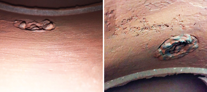
Image 2. Root cause analysis showed that metal chaplets used during manufacturing initiated the failure mechanism.
Chaplets are usually comprised of different metallurgy from the metal being poured and can create a weak area if left in place. Image 2 shows areas that were either utilized for chaplets or are core sand clean-out plugs, which were excavated and welded.
The engineers eliminated the need for chaplets during the pouring process by using 3-D technology, which allows for the manufacturing of the cores in a hybrid design that will lock them in place inside the mold. By using this method, the sophisticated technology averages the wall thickness, minimizes core shift and minimizes welding. The volute areas were examined by the bore scope and properly cleaned.
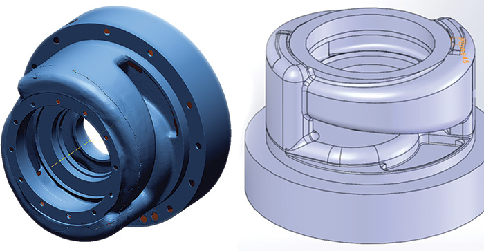
Figure 1. Data was captured using scanning techniques and the twin volute was modeled in CAD.
Casting Defects
In the volute crossover areas, Hydro noticed a significant amount of flash on both sides. This is created by core lift where two cores are jointed together. While the 3-D printing method will not eliminate the need for separate cores, it allowed Hydro to move the core split to an area that is accessible for grinding. The 3-D printed cores were 0.005-0.20-inch accurate dimensionally in the x, y, and z axis. This gave the engineers precision core filament during the mold building process.

Figure 2. CFD analysis performed for both extreme and optimum condition
CFD Solidification Analysis
Initial analysis of the raw material identified the areas of concern to help direct the design of the riser pattern and also highlight the preferred area of the in-gates. Risers are cylindrical tubes insulated by exothermic sleeves to generate heat once they are filled with liquid metal.
They are typically placed in “feed zones,” which are areas that could potentially cause a shrinkage defect during the solidification of the metal.
The function of a riser is to keep its metal warmer than the metal within its feed zone to direct any possible defect inside of it. In-gates are where the metal enters the main body of the casting during the pouring process. Ideally, they are located toward the bottom of the casting to minimize velocity or turbulence inside the metal.
Initial Material Density Results
Two major feed areas were addressed by adding risers and chills to help direct the solidification of the metal. Risers were placed to direct solidification impurities from the base metal.
Areas that are unable to be supported by risers should have chills installed to cool down the heavy section as the liquid metal enters the mold.
Chills are pieces of solid metal that are placed securely in the sand mold to help cool the metal over the heavy section as it fills. The combination of the two feeding methods allowed Hydro to produce a premium product with minimal defects.
Final CFD Analysis: Extreme Conditions
The software package allowed designers to look at the pouring conditions in both optimum and extreme conditions. An engineer inputs the optimum conditions—such as pouring temperature, pouring time, atmospheric conditions and mold materials—into the system. The CFD software does its work with the understanding that this is the optimum when pouring the alloy, with a range from 0-1 where 0 is optimum and 1 is extreme. This process evaluated the casting at 0.9 as optimum and 0.999 as extreme. With this information, engineers designed the gating and riser system to handle the most extreme conditions when pouring the alloy.
These indications showed the predicted shrinkage in a worst-case scenario. This is minimal and can be addressed during the rough machining stage. Even in extreme conditions, these predicted shrink areas might not exist. This is a theoretical calculation that has proven to be accurate. These areas are then evaluated during the RT process.
Final CFD Analysis: Optimum Conditions
This is a similar analysis, but in the optimum condition. All the indications are in the riser tubes, and the main casting body is free of defects. Hydro provided the foundry a pour data form for each individual casting and then meets those specs.
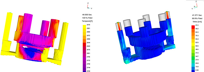
Figure 3. Temperature gradient
Temperature Gradient Analysis
When studying the flow of metal, one must find a balance that allows the metal to enter the mold fast enough to fill it before it begins the solidification process. At the same time, it must minimize turbulence. The main area of concern in this case was placing the risers where they would stay hot the longest. Hydro used a dual Sprue method to bring the metal in equally on both sides during the pouring process. This fed the critical geometry areas quickly and minimized turbulence as the feed was operating from two directions.
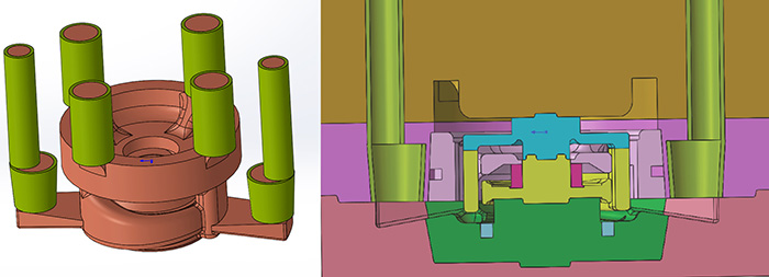
Figure 4. Gating and risers design and sand mold design
Velocity Analysis
Velocity control is critical in all aspects of pouring. High velocity triggers gas reactions, premature freezing of metal fragments and inconsistent feeding. This is a critical step to ensure that the gating has the proper choke to minimize turbulence during the pouring process. Typically, it is important to keep the velocity below 30 inches per second. Choke points are how foundry workers control the speed of metal. The software package has a program to help design choke points when creating the gating system.
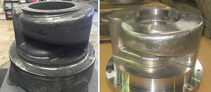
Image 3. (left) Rough casting and (right) casting after machining and the final inspection
Conclusion
Simulating a casting before manufacturing any tooling proved to be a great success. By studying the material density in optimum and extreme conditions, temperature gradient and velocity, project personnel minimized the risk of both the manufacturer and the end user. Manufacturers were able to eliminate the use of chaplets and create hybrid cores that yield premium results.
The fully refurbished element has been installed and is operating with vibration levels considerably improved over the original design.

Figure 5: Original bundle with 1st stage impeller old design
Pressure Pulsations at Vane Frequency
Pressure pulsations at vane frequency are initiated by each of the vanes of the impeller passing close to the volute cutwater lip. These pulsations can affect vibration of the machine. Traditional methods to reduce these pressure pulsations involve increasing the distance between the impeller vanes and lips to allow time, distance and viscosity to smooth out this pressure wave. Unfortunately, this technique does not come without penalty and affects both pump head and efficiency.
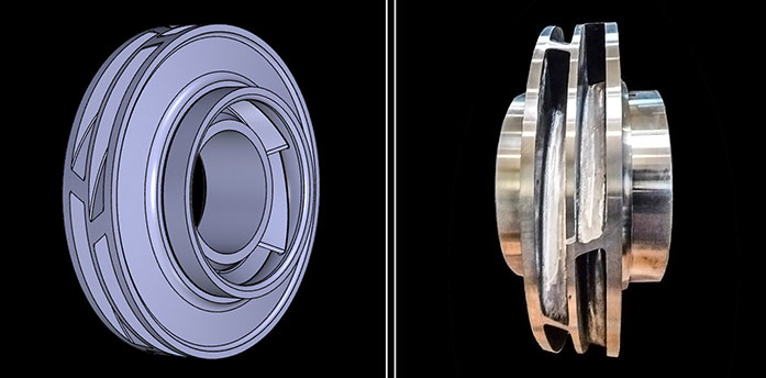
Figure 6: Design and manufacture of upgraded 1st stage impeller with center rib, staggered and raked.
To reduce the pressure pulsation without adversely impacting the machine’s hydraulic performance, Hydro designed and installed staggered and raked vanes to the impeller. This required a center rib to be designed into the impeller around which the impeller vanes can be staggered.
This means that the vane tip width passing the cutwater is halved lengthwise and the rake angle of the blade spreads this passing over a greater time/distance.
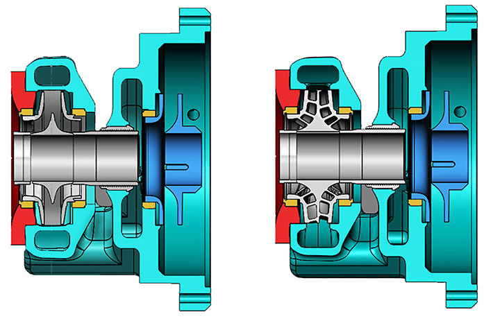
Figure 7: Original first-stage impeller versus upgraded 1st stage impeller design
Conclusion
Vibration is an important indicator of future pump reliability. When analyzing vibration data, it can be important to work with a company that also has hydraulic design experience. When vibration data indicates that a vane pass frequency problem exists, their engineering experience can not only diagnose the problem but also design an impeller to improve the pump’s reliability. In this case the vane passing pulsations were dramatically reduced by providing a staggered, split-vane design.
See more at (Part 1)– https://www.pumpsandsystems.com/pumps-pumps-rotary-pumps/june-2017-using-latest-technology-refurbish-50-year-old-pump-element
See more at (Part 2)– https://www.pumpsandsystems.com/pumps-rotary-pumps/august-2017-using-latest-technology-refurbish-50-year-old-pump-element-part-2
