Repair is an Opportunity to Improve Pump Performance

Written by: Bob Bluse, Hydro East Inc.
Publisher: Pumps & Systems / February, 2012


Often all that is needed to improve a pump’s reliability and performance is to provide a high quality inspection and repair. Over time a pump may have been repaired by more than one service provider with varying levels of engineering and technical experience. Tolerances may have been opened up, fits and concentricities may have been lost and materials may have been changed, all of which contribute to reduced performance, loss of reliability and more frequent repairs.

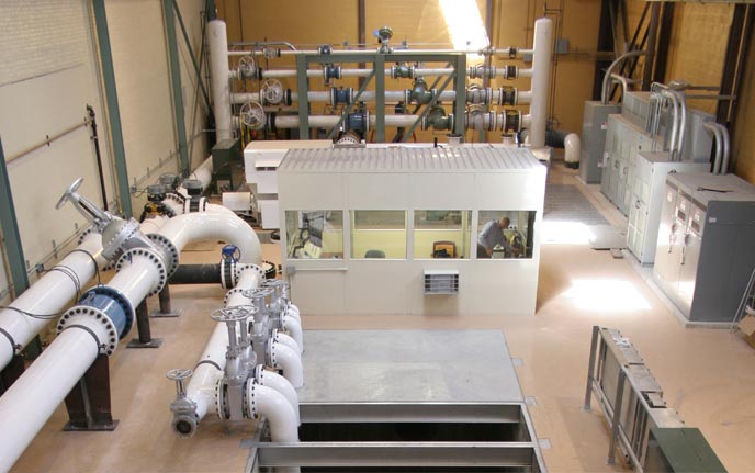
This article highlights the opportunity seized by a coal-fired power station to upgrade a Westinghouse Vertical Pump during the repair process.


Background:

The Power Plant’s Unit #4 “Alpha” Circulating Water Pump was scheduled for repair and in the process of removal, the sister pump #4 “Bravo”, exhibited severe vibration and failed in a manner which was believed to have been a result of a broken shaft. The Alpha pump was put back into service and the Bravo pump removed and sent to the repair facility for inspection and emergency repair.


Observed Pump Condition:

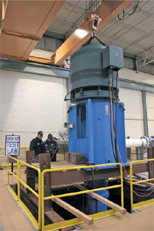
The general condition of the Bravo pump when received at the repair facility was much worse than anticipated with the top column flange broken about half way around. The entire pump had been hanging from this broken joint leaving a gap of ¼” to ½” at the opening. The keyed coupling (internal to the pump) used to join its two shafts was broken in several pieces, the shaft journals were severely worn to one side and the impeller vanes & suction bell liner surface were also severely worn as expected, considering the significant pump damage.


After disassembly of the pump, it was also observed that the shaft enclosing tubes had spun in their fits due to not being fitted with any anti-rotation mechanism. This rotation caused damage to the ‘O’-ring fit areas at both ends of the enclosing tube assembly resulting in loss of proper flush water supply to the pump bearings below the packing box. Another issue observed during inspection was that part-to-part alignment of major pump components utilized dowel pins, which are very difficult, if not impossible, to verify.


Continue reading

Air Void Testing for Safety-Related Feed Pumps in Nuclear Power Plants

Written by: Dr. T. Ravisundar, Ravi Somepalli, and Bill Nagle of HydroAire Inc.
Publisher: Pumps & Systems / December, 2011


An Interesting Challenge and Cause for Collaboration

A major nuclear power company approached an independent Pump Performance Test Lab in Chicago to discuss a series of tests for their Pacific 4” BFIDS in safety-related service. These auxiliary feed water (AFW) pumps were utilized in two pressurized water reactor plants to supply backup cooling water to the steam generators in the event the main feed water source was interrupted. The plants had been designed to utilize an air void between two motor operated valves to keep separate two different suction sources to the pump. The Nuclear Regulatory Commission (NRC) guidelines dictated that no more than a 2% air void could be passed through the pump to reliably assure its safety-related function. The nuclear power plant engineers believed the pump could ingest a greater margin of air without damage or impairment to pump performance. The NRC gave the nuclear power company an opportunity to demonstrate the capability of this pump by allowing them to conduct and monitor a series of transient air-void tests at the independent Pump Performance Test Lab.


The independent pump performance test lab in Chicago, IL.

Engineers Working Together to Define Test Scope

The nuclear power plant engineers worked closely with the engineers at the Test Lab and a third party engineering consultant to develop the scoping document which defined the tests needed to demonstrate the pump’s capability under a range of scenarios. To design these tests, the team first reviewed the system configuration at the plants.

For added safety, each unit at each plant had one motor driven and one diesel engine driven AFW pump. Each AFW pump had been installed and aligned through valves and piping to take suction from either the non-safety related condensate storage tank (CST) or the nuclear safety related essential service water system (SX). The SX system is the nuclear safety related system that is connected to the plants ultimate heat sink (UHS), which is raw river water. As can be imagined, there is considerable difference in the purity of the water between the CST water and the SX water. Therefore, both plants intentionally built in the air void as a provision for separating these two systems to reduce the chance of SX water contaminating the clean condensate side of the system.

After thorough review, the team issued specifications for ten different sets of test cases which encompassed several operating conditions and well over 35 test scenarios. The tests would cover injection of different void volumes into the pump operating with several variables, some of which included different flow rates, suction pressures, and pump statuses (i.e. operating pump, idle pump with a pump start while suction is being transferred, etc.).


Configuring the Test Lab

Once the scope had been clearly defined and agreed upon, the Test Lab engineers set out to configure the Test Lab in a way that would duplicate almost identically the plant’s AFW suction piping set-up. Within 10 days, the Test Lab was configured with a booster pump installed with a variable frequency drive to simulate the SX system as closely as possible so that the safety-related AFW pump could be operated within the same environment as it would function in the plant. The SX water source came from the Test Lab’s 38,000 gallon suppression tank which was fed through the booster pump. The CST, which was simulated by the Test Lab’s suppression tank, was not sent through the booster pump.


Continue reading

Impeller Failure Solution at a Vietnamese Power Plant

Written by: Kwa Soo Teck, Phu My 3 Power Station (Vietnam), & Chandra Verma, Hydro Australia
Publisher: Pumps & Systems / September, 2011


Phu My 3 BOT Power Station, a Vietnamese power station using combined cycle gas turbine technology and operating at 749 megawatt capacity, had been experiencing some problems with their vertical pumps. The station asked Hydro Australia to assess the damage and assist with a solution.


The power plant in Vietnam


The vertical pumps were used for the circulating water system. The impeller material was a super duplex and the product being pumped was sea water. Over a period of three years, Phu My 3 had experienced catastrophic failures with the impellers and were unsure of the cause. The first pump was installed in Sept 2003 and the first blade failed in September 2008; the second failure occurred in Sept 2009 and a third failure occurred in June 2010.

On viewing the damaged impellers, which weigh 850 kilograms, it was obvious the quality was poor. The first step in the process was to send over an engineer with a Romer Arm, a 3D coordinate measuring instrument, to reverse engineer the impeller. This data could be used to analyse the existing impeller design.


Continue reading

Performance Testing for a Rebuilt Pump

Written by: Jeff Johnson, Hydro, and Bill Rademacher, BP

Publisher: Pumps & Systems / April, 2011


A refinery’s vertical pump passes the test, verifying its performance before installation.

The rotating equipment engineers at BP’s Whiting Refinery in Indiana approached the support team at a pump service center in Chicago to discuss testing its rebuilt vertical turbine pump in the center’s new 5,000-horsepower test lab. Their pump, a Johnston 40 GMC pump, is one of four pumps used for the refinery’s rainwater drainage and process sewer system. This pump is the first pump in line and has a diffuser built onto the suction bell to direct flow into the pump.

Two other pumps are in line behind this pump and a fourth pump is to the side. All are mounted in a large concrete channel system. BP had implemented a specially designed suction strainer on this pump to minimize potential sump vortexes from entering the pump through the suction side of the impeller.


Hydro’s 5000 HP Test Lab in Chicago, IL


This vertical pump had been rebuilt and modified by trimming the impeller and opening the inlet diameter (ID) of the suction bell to improve the flow path characteristics into the impeller eye opening. The refinery wanted verification that the modifications made to the pump resulted in the calculated decreases in horsepower and NPSH required. The goal of the tests, as defined by the refinery, was to determine the operating characteristics, including head (total discharge head—TDH), flow and horsepower, as well as the minimum submergence level of the pump so it could adjust its operating set points and submergence level alarms to avoid cavitation damage.

As the pump service center maintains an “open door” policy, several individuals from the refinery visited the test lab over a two-day period to observe the testing process, which proved to be an educational experience.


Johnston 40 GMC vertical pump on the test stand


The Performance Test

Because BP provided the 1,000-horsepower pump motor, the service center engineers were able to set up both the vertical pump and the motor in the test lab. Using this set-up, the service center engineers would be able to help BP obtain an accurate understanding of how their pump would perform in the field.

The service center engineers conducted the performance test and used a validation program to calculate the efficiency using data inputs such as flow, horsepower, barometric pressure, suction level, discharge pressure, temperature and specific gravity of the water, diameters of the piping system and the location of discharge collection points.

The pump’s best efficiency point (BEP) was proved at just under 18,000 gallons per minute, at about 130 feet of head, using about 750 horsepower. Proving the BEP of its pump will enable BP to determine how it should operate the pump most efficiently in the field.


The Minimum Submergence Level

The service center engineers performed a submergence test to show BP where its low sump levels should be set. Cavitation was anticipated at a depth of 39 inches and the service center engineers were able to show the pump’s performance at its lowest submergence point before cavitation could occur, which was 42 inches. The minimum submergence levels were proved so that BP could ensure the best level settings could be achieved in the field without causing damage to the pump.

Ironically, the test pool turned out to be a close replication of the refinery’s sump. This enabled the service center engineers to confirm BP’s suction strainer had been effectively designed. The witnesses to the test could visually see how the suction strainer sheared vortexes that had developed in the sump at low submergence levels.

Continue reading

Repair and Renewal Offer Fast Turnaround and Cost Savings

Written by: Ron White & Ben Roberson, HydroAire Inc.

Publisher: Pumps & Systems / February, 2011


A “temporary” repair results in five years of service.

Five years ago, an engineered pump service center in the Midwest received a call from a large municipal sanitary district. One of the company’s four submersible pumps had tripped the overloads. This 890-rpm unit operated on variable frequency drives that adjusted the motor speed to match the fluid inflow. Once it had been reset, the 290-horsepower, 42-inch diameter axial flow pump exhibited significant vibration before failing. The pump was removed and sent to the service center where it was cleaned, disassembled and inspected by a team of skilled professionals dedicated to repairing submersible pumps.


Figure 1. 290-horsepower submersible pump upon arrival at the service center


The Assessment

The initial inspection revealed that a large chunk of concrete debris from nearby sewer construction caused the submersible pump to fail. The inspection also showed that the pump had several problems:

  • A section of the trailing edge of one of the impeller vanes was broken.
  • The rotating ring was missing.
  • The impeller hub and lower mechanical seal had cracked and caused damage to the shaft keyway.


Figure 2. The cracked impeller hub


When the municipality inquired about replacement parts from the OEM, delivery was estimated at a 12- to 14-week turnaround time on a new impeller from Europe. The municipality could not afford to be without the pump for an extended period of time. Having a great deal of experience with submersible pumps, the dedicated submersible repair division proposed a temporary solution to get the pump repaired and back into service until the municipality could obtain a new impeller from the OEM.


Continue reading