Maintenance Technology
September, 2007
The first installment of this series highlighted general guidelines regarding the selection of competent non-OEM pump repair facilities. This month, these guidelines are discussed in more detail.
You get what you inspect. That said, a pump user must have a repair specification. It may or may not be identical to the specification used by the non-OEM competent pump repair shop (CPRS). Where the specification or checklist of the CPRS differs from the one of the user/purchaser, the issues need to be explored and the ramifications of any deviations understood. At that time, waivers are issued and details of the understanding are documented.
In any event, unless a process pump manufacturer gives specific and different values or measurements for a particular make, size or model, experience shows the guidelines in this article to be useful”and valid. Even an in-house pump shop would benefit from making it a habit to use and apply the following assembly dimension checklist. Some of the listed diametral clearance and/or interference tolerances will be stricter than what certain pump manufacturers allow (for reasons of internal cost savings, perhaps). But, then again, this simply illustrates the opportunities to improve on some OEM products.
Best-of-Class user shops often make copies, laminate them and either hand them to each of their shop technicians or post them near mechanic/technician workstations. CPRS facilities use similar approaches to disseminate the information in Sidebar 1, Best-of-Class Pump Specifications, to their staffs.
Beyond the actual specifications listed in Sidebar 1, there are other Best-of- Class type guidelines to consider when rebuilding a pump. A CPRS certainly considers them.
Shop tools and equipment
The use of proper shop tools and shop equipment is of critical importance to reliability-focused pump users. While it is well beyond the scope of this article to explain all shop tools and their proper use, the following examples will highlight the issue.
Take, for instance, collet drivers for certain impellers. Unless this special tool is used for vertical turbine pumps (VTPs) equipped with tapered collets, the impeller will not be secured properly to the pump shaft.
Likewise, unless a shop uses the proper heating technique for bearings and coupling hubs, achieving quality workmanship will be nearly impossible. Therefore, a modern eddy current (induction) heater is high on the list of necessary shop equipment.

Accurate dimensional mapping of pump casing and rotor geometry requires contour measuring equipment. Some of this equipment is portable, often called Coordinate Measuring Machines; other types are fixed machines. All use specialized software. Despite this type of built-in automation, expertise on the part of the CPRS employees is always a great advantage.
The physical tools also include process control procedures and quality verifications steps. The policies of a CPRS are enunciated and written copies are made available to anyone who asks for them. There are no secrets”and competent shops will not attempt to be secretive. The CPRS will share this information freely with the customer.
Rotor balancing
All impellers, irrespective of their operational speed, should be dynamically (spin) balanced before installation, either single or two-plane. Two-plane balance is required for a wide impeller, when the impeller width is greater than one-sixth (1/6) of the impeller diameter. ISO balance Grade 2.5 is recommended here.
There is no doubt that dynamic balancing of the three major rotating pump components”shaft, impeller and coupling”will increase mechanical seal and bearing life. All couplings of any weight or size should be balanced, if they are part of a conscientious and truly reliability-focused pump failure reduction program. Couplings that cannot be balanced simply have no place whatsoever in industrial process pumps.
The preferred procedure for balancing a rotating unit is to balance the impeller and coupling independently, and then the impeller and coupling on the shaft as a single unit. Another method is to balance the rotor one time only as an assembled unit.
Increasing pump efficiency
Computer tools available to the CPRS often will favor designing new, more efficient impellers. Certain installations, however, also will benefit from a simple change to another, already existing and tested impeller geometry. Some impellers are readily available as low-, medium- and high-capacity configurations. Seriously consider a CPRS that knows and shares regarding pump efficiency matters.
Low- and high-capacity impellers. . .
In the majority of pump casings, it will be possible to install impellers of different widths for low- or high-capacity performance. Because of the variations in the design of the impeller vanes (angularity and number of vanes), it is somewhat difficult to predict their performance. Still, for a given impeller with a given angularity and number of vanes, one can reasonably anticipate the performance of the narrow, medium and wide impellers. In Ref. 1, the reader will find actual test data comparing the performance of impellers with three different peripheral widths. In the example shown in Ref. 1, the normal impeller exit dimension was 2, whereas the high- and low-capacity impellers were 2.75 and 1, respectively. Capacities ranged rather widely from 5000 gpm to 9000 gpm, and efficiencies bracketed 82% to 88%. It also can be said that the performance of different impellers in the same casing is, to some degree, related to specific speed and that efficiency increases with higher capacity impellers. Over-sizing of impellers, though, is rarely recommended.

Impellers with different numbers of vanes. . .
Certain pump applications require the pump performance curves to have differently shaped head-capacity curves. For instance, to overcome friction only, as in pipeline service, the highest head per stage, or a very flat curve is desirable. To overcome static head or to have pumps run in parallel as is customary in process or boiler feed services, a continuously rising head-capacity curve is usually needed for highest possible efficiency.

There are different ways to vary the shape of a head-capacity curve and generalizations are not always accurate. The following four points, however, should be noted as they again show why working with a resourceful and knowledgeable CPRS is so very important.
1. If, say, the existing impeller has six or more equidistant vanes, producing a new impeller with only five equidistant vanes may be of interest. The fewer the number of vanes, the steeper the curve. When vanes are removed, the effective fluid discharge angle decreases due to increased slip. This moves the peak efficiency flow point to the left. The efficiency will also drop, the lowest being at the least number of vanes. In the case of a seven-vane impeller reduced to four vanes, the efficiency will drop about four points.
2. If a different head-capacity curve shape is required in a given casing and the same peak capacity must be maintained, a new impeller must be designed for each head-capacity shape. The steeper the head-capacity curve, the fewer will be the number of vanes, with a wider impeller used to maintain the best efficiency capacity. For example, a 7-vane/27-degree exit angle will have a flat curve and a narrow impeller, whereas a 3-vane/15-degree exit angle will have a steep curve and the widest impeller. In other words, to peak at the same capacity the impeller discharge area must be the same, regardless of headcapacity relationships. Also, for a given impeller diameter, the head coefficient will be the highest for the flattest curve. The efficiency of the above impellers can be maintained within one point.
3. The slope of a head-capacity curve also can be increased by trimming the impeller outer diameter at an angle, with the front shroud diameter being larger than the back (hub) shroud.

4. Extending the impeller vanes further into the impeller eye can increase the slope of the head-capacity curve. An extreme version of this case is the addition of an inducer in front of the impeller. The naturally steep head-capacity performance of the axial flow inducer is then added to the flatter performance of the lower specific speed impeller. As one compares the NPSHr trend of an inducer-less impeller with an impeller fitted with a standard inducer and an impeller with specially engineered inducer, it will be noted that off-the-shelf standard inducers may lower the NPSHr only in the vicinity of BEP operation [Ref. 1].
Restriction orifices to modify pump curves. . .
In low specific speed pumps, where impellers already are very narrow and low-capacity or narrower impellers cannot be cast, capacity reductions can be obtained by using restriction orifices in the pump discharge nozzle. Refs. 1 and 2 contain illustrations that convey these points. In all instances, a CPRS can predict the anticipated or achievable performance change when the discharge is throttled with different size orifices. If the performance of a pump absorbing 1000 kW is improved by just one percent and power costs $0.07 per kW/hr, the yearly operating cost savings will amount to $6132.
Wear materials for improved energy efficiency. . .
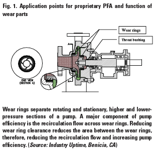
Fluid processing industries and CPRS facilities have embraced the use of current generation composite materials in centrifugal pumps to increase efficiency, improve MTBR (mean-time-between-repairs) and reduce repair costs. One such material that has been used successfully by major refineries is a proprietary PFA, a carbon fiber composite with a uniquely low coefficient of expansion and superior temperature stability. As noted in Refs. 1, 3 and 4, this one particular high-performance polymer composite has replaced traditional metal and all previous generation composite materials in pump wear rings, throat bushings, line shaft bearings, inter-stage bushings and pressure reducing bushings. The properties of this particular product eliminate pump seizures and allow internal rotating-to-stationary part clearances to be reduced by 50% or more.
For good reason then, composite wear materials are included in the 9th (2003) and later editions of the American Petroleum Institute™s pump standard, API-610. The various application points are illustrated in Fig. 1.

Only the low-expanding, high-temperature-capability, proprietary PFA materials have proven to eliminate pump seizures, provide dry-running capability and greatly reduce the severity of damage from wear ring contact. Users report freedom from pump seizures during temporary periods of suction loss, off-design operation, slow-rolling or start-up conditions. When the upset condition has been corrected, the pump continues operating with no damage or loss of performance. Conversely, when metal wear components contact during operation, they generate heat, the materials gall (friction weld), and the pump seizes. This creates high-energy, dangerous failure modes, which can result in extensive equipment damage and even the potential release of process fluid to atmosphere.
CPRS engineers know that correctly chosen proprietary PFA wear parts undergo only about 15% of the thermal expansion of certain other high-performance polymers. This is a very important distinction that contributes to the success of this engineering material. To re-state, properly applied and configured pump wear components (excluding sleeve bearings) made from this material are certain to reduce the risk of damaging expensive parts. This means reducing repair costs and mitigating safety and environmental incidents.
Moreover, reducing wear ring clearance by 50% increases pump performance and reliability through increased efficiency, reduced vibration and reduced NPSHr. The efficiency gain for a typical process pump is 4-5% when clearance is reduced by 50% [Ref. 5]. Minimized wear ring clearance also increases the hydraulic damping of the rotor, reducing vibration and shaft deflection during off-design operation. The lower vibration and reduced shaft deflection increase seal and bearing life and help users achieve reliable emissions compliance. This reduction in clearance also reduces the NPSHr on the order of 2-3 ft (~0.6-0.9 m), which can eliminate cavitation in marginal installations.
Field experience shows remarkable success when installing proprietary PFAs to achieve all of these benefits. For example, one refinery installed such wear rings and line shaft bearings to eliminate frequent seizures in 180 F condensate return service. These condensate return pumps subsequently have been in service for many years without failure. Another user improved the efficiency and reliability of two gasoline shipping pumps by installing proprietary PFA wear rings, interstage bushings and throat bushings. The shipping pumps also have been in service for many years without failure or loss of performance. Hundreds of other services and applications have benefited from properly selected composite wear components; they include pumps in light hydrocarbons, boiler feed water, ammonia, sour water and sulfuric acid.

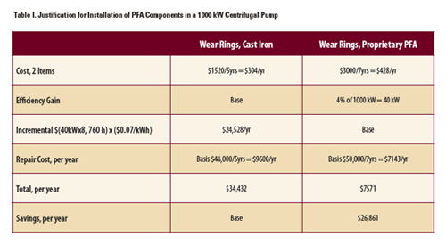
As usual, there are many ways to investigate the cost justification for upgrading to high performance proprietary PFAs in pumps. Note, in Table I, how a good justification incorporates the value of efficiency gains in a 1000 kW centrifugal pump, where clearance was reduced by one-third.
Based on calculations in Table I, a one-time incremental outlay of $3000-$1520 = $1480 returns $26,861 per year for seven years. The first-year payback ratio is $26,861/$1480”about 18:1. Using other parameters one could reasonably arrive at even higher payback ratios. Among these are the imputed cost of avoided fire incidents and the value of re-assigning freed-up workforce members to proactive failure avoidance tasks [Ref. 4].
This type of cost justification is straightforward and sufficiently accurate to determine the path forward. The CPRS should take the lead in selling his upgrade services by offering tentative cost justifications. Of course, the owner-operator must be responsive and provide suitable plant statistics, as available.
Documentation
If you are considering a non-OEM repair operation, keep in mind that a CPRS”a truly competent pump repair shop”should be able to produce many detailed, real-world engineering evaluation samples of its work. This documentation should indicate that the shop is following the Best-in-Class type of guidelines included in this article. Ask to see these samples, which may take the form of reports and/or case studies. When it comes to the proper maintenance and rebuilding of their critical equipment, reliability-focused pump users want information up front”not surprises later on.
Coming in Part III
In the next installment of this series, the authors provide specific assessment criteria for those considering entrusting their pumps to a non-OEM rebuilder.
References
1. Bloch, Heinz P. and Alan Budris, Pump User’s Handbook: Life Extension, (2006) Fairmont Publishing Company, Lilburn, GA, 2nd, Revised Edition, ISBN 0-88173-517-5
2. Bloch, Heinz P. and Claire Soares, Process Plant Machinery for Chemical Engineers, (1998) Butterworth- Heinemann, Woburn, MA. 2nd, Revised Edition, ISBN 0-7506- 7081-9
3. Bloch, Heinz P., “Twelve Equipment Reliability Enhancements with 10:1 Payback”, Presentation/Paper No. RCM-05-82, NPRA Reliability & Maintenance Conference, New Orleans, LA, May 2005
4. Bloch, Heinz P., “High Performance Polymers as Wear Components in Fluid Machinery,” World Pumps, November, 2005
5. Bloch, Heinz P. and Fred Geitner, Major Process Equipment Maintenance and Repair, (2006) Gulf Publishing Company, Houston, TX, 2nd Edition, ISBN 0-88415-663-X
About Hydro Inc.
All photos in this non-OEM pump rebuild series, including the cover photo of the July 2007 issue of Maintenance Technology, have been provided by Hydro Inc. (www.hydroinc.com). Founded in 1969 and headquartered in Chicago, Hydro is the largest independent pump rebuilder in North America, providing support to pump users around the world.
http://www.mt-online.com/article/0907_non_oem_pump_rebuild_shops

