Engineering a Long-Term Solution

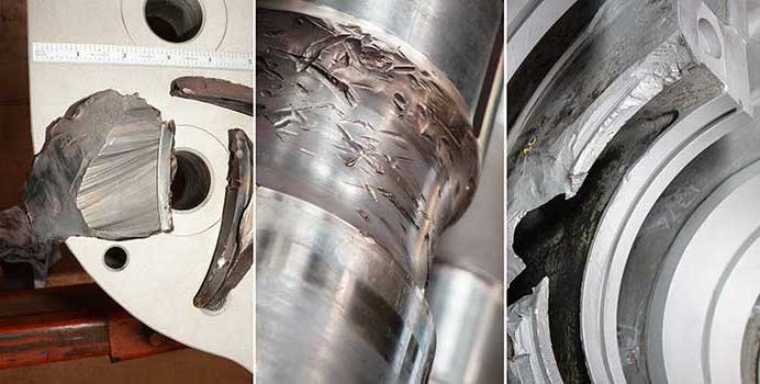
Figure 1. The pump as received

Many pumps in operation today were designed and manufactured decades ago. As plants require increased capacity, pump systems are expected to meet these higher process flow demands. Without an impeller rerate or change in speed, this increased capacity can be achieved in one of two ways. The individual pumps can supply more flow to the system, resulting in operation out on the pump curve. Alternatively, capacity can be increased by operating more pumps in parallel; in this case operation is pushed back on the curve, as operating another pump in parallel requires less flow from each individual pump to meet total system demand.

Either operational change results in a move away from the pump best efficiency point (BEP). As a result, the original designs and hydraulic characteristics no longer effectively meet plant requirements and detrimental effects from hydraulic instability can occur.

By way of example, this article will discuss a fertilizer plant in the Gulf of Mexico that had a boiler feedwater pump unit that was experiencing performance problems after a significant plant expansion project. Unfortunately, it was not the first time this particular unit had experienced a loss of capacity; the pump had been in operation only 18 months prior to the current issue.


Root Cause Analysis Uncovers Casting Defects

Efficiency and reliability are at the forefront of a successful pumping system. As such, unplanned outages can be a detrimental disturbance to the overall operation. In this case, the end user’s high pressure multistage  BB5 barrel pump was experiencing severe vibration, unstable performance, and failure in the field leading to unit shutdown.

This particular unit, used in boiler feedwater operations, is critical to the plant’s uptime and throughput. Furthermore, continued failures can cause growing costs due to inevitable maintenance and repairs, often overlooking a long term solution. With each unplanned outage, the plant could face a significant loss in capital.

Previously, the pump had been running for six months before experiencing catastrophic failure, requiring a shutdown and removal for further analysis. Initially, the unit’s damaged components were repaired by welding, and the volute was reassembled and installed for use. Upon its installation, the power plant placed the unit back into service but encountered a second emergency shutdown after two months in operation.

Video: https://vimeo.com/362808909

Source: https://www.pumpsandsystems.com/root-cause-analysis-uncovers-casting-defects-critical-boiler-feedwater-unit

Hydraulic Rerates & Pump Efficiency

During a mechanical seal replacement at a major gas plant, a reliability engineer identified that their API OH2 centrifugal pump was operating below the Minimum Continuous Stable Flow (MCSF).

In this case, Hydro Rocky Mountain partnered with HydroTex Deer Park‘s engineering team to provide the customer with an innovative solution by utilizing the existing casing and providing a redesigned impeller to optimize the overall efficiency and life cycle of the unit.

Watch as Ares Panagoulias and Glen Powell, of Hydro’s test lab, examine the historic operating conditions in regard to the pump’s best efficiency point (BEP) and provide a performance test to validate the upgrades and modifications.

Case Study: Hydraulic Rerates & Pump Efficiency from Hydro, Inc. on Vimeo.

Read the full article on World Pumps: worldpumps.com/ancillary-products/features/seal-replacement-reveals-causes-of-vibration/

Close Inspection Solves High Thrust Bearing Temperature Problem

Careful analysis identified the issue with this multistage, oil transfer pump.

Written by: Gary Dyson (Hydro, Inc.)
Publisher: Pumps & Systems / August 2014


A multistage BB5 diffuser machine in oil transfer service in the Middle East had been in operation for many years without problems. After a routine maintenance strip down and rebuild, the pump experienced a high thrust bearing temperature of 105 C, which caused it to alarm and shut down. The temperature range had previously been 75 C to 85 C.

This case study describes the method used to solve the high bearing temperature problem and outlines the flow physics that contributed to the high thrust bearing temperature. The customer contacted an engineering services company after the original pump manufacturer failed to remedy the problem.

The company’s forensic approach to this problem involved two distinct methodologies:

  • Diligent and in-depth analysis of site data relating to 
the problem
  • Rigorous scrutiny and analysis of the pump geometry and build against the background

The engineering services company identified several scenarios that could cause this temperature rise, then narrowed down the list to establish a root cause.

Site Data Analysis

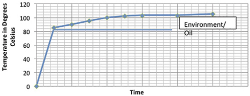
The behavior of thrust bearing pads during startup is seldom investigated. The temperature rise of the pads can be attributed to two distinct causes—thrust developed during startup and environmental and oil conditions (see Figure 1).

thrust-bearing-pad-behavior

Figure 1. Behavior of thrust bearing pads based on thrust and environmental conditions (Article images and graphics courtesy of Hydro Inc.)

The significant finding from this data was the temperature rise associated with thrust. The pump could not achieve the temperatures measured prior to maintenance in its current condition. The total thrust bearing temperature includes the oil temperature and environmental conditions.

Based on comparisons with previous site data, both the thrust and oil cooling had altered. Analysis of the temperature data at the motor bearings, which were experiencing oil temperature increases of 10 to 15 C, further supported the conclusion. Continue reading