Hydro’s condition monitoring solution, Centaur, is currently being used to monitor rotating machinery at a Gulf Coast terminal facility. Through Hydro’s Centaur system, real-time vibration amplitude levels and temperature levels are collected and stored at several measurement locations on compressors and their drive trains. Analysts at Hydro’s Monitoring and Diagnostic Center help to evaluate the collected data. They use their subject matter expertise to make recommendations to the end user when they identify actions that could minimize downtime and maximize the lifespan of the monitored machinery.
Using industry standards as a guideline, alarm thresholds were generated for each machine. Centaur’s engineers worked with the end user to set up automated email alerts delivered through the web-based analytical software when targeted alarm thresholds are crossed.
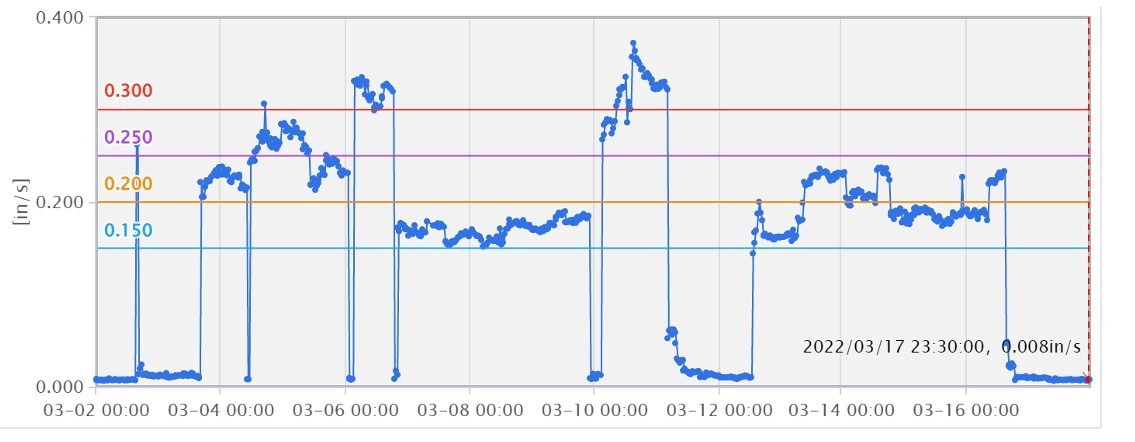
In mid-March, the purple alarm 2 threshold (>0.250 ips RMS) and the red alarm 3 threshold (>0.300 ips RMS) were crossed by multiple sensors in multiple directions. The trend plot below shows an upward trend in vibration amplitude levels on the monitored compressor.

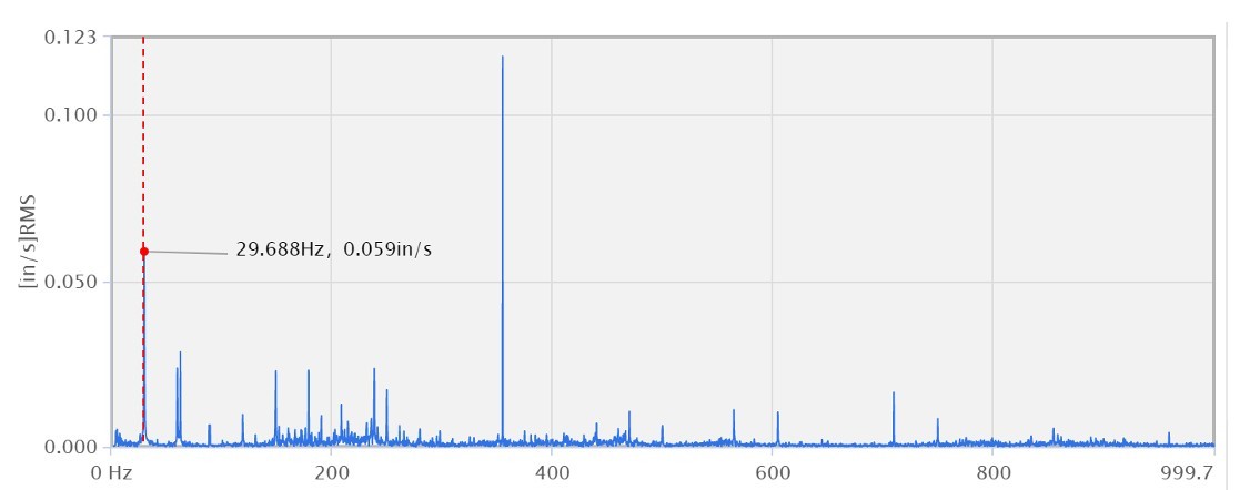
When the Centaur engineers reviewed the vibration data, they identified a dominant excitation frequency at 1x run speed (29.688Hz) with harmonics present. Knowing that the compressor skid, including the compressor and motor bases, were never fully grouted, they suspected that misalignment may be the root cause of the elevated vibration amplitude readings. Misalignment occurs when there is an offset between the centerlines of the driving component and the driven component. It can result in high radial forces, high axial forces, or a combination of both.

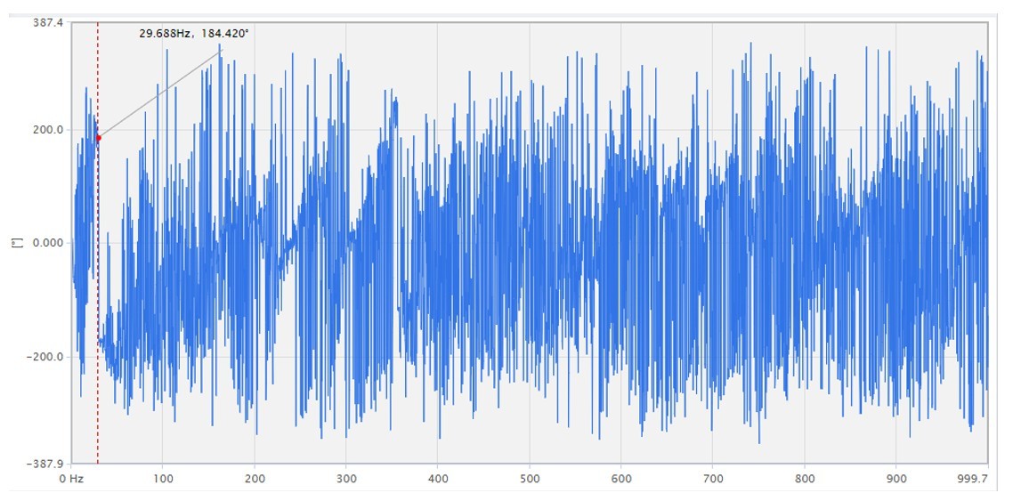
To further validate that misalignment might be influencing the high vibration, the Centaur engineers looked at the phase data collected. The phase analysis performed between the compressor inboard sensor location and the motor inboard sensor showed a significant difference in phase between the two locations. The phase difference chart below shows a 184.420° phase difference between the compressor inboard sensor and the motor inboard sensor. The phase angle is indicative of a potential misalignment condition being present between the coupled components.

To confirm our suspicions, Hydro reached out to the end user’s on-site personnel and suggested that the alignment be checked. Site personnel checked the alignment and confirmed that the compressor and motor were out of alignment and corrected the issue.
Recognizing the likely root cause of the high vibration and having the tools within Centaur’s analytical software to provide supporting evidence saved the end user time and money in diagnosing the problem. The cause of the high vibration was addressed quickly, limiting any damage to the compressor components and returning the equipment to stable behavior.
