
Additive manufacturing also improves geometric tolerances.
Written by: Jesse Stinson (Hydro Parts Solutions) & Werner Barnard (Hydro Inc.)
Publisher: Pumps & Systems / March 2, 2015
An increasing number of industrial plants are reducing the spare parts inventories stored at their facilities. At the same time, they are replacing fewer pumps because of capital constraints and have determined that remanufacturing existing equipment is the best path forward. Many of the pumps within these facilities have exceeded 50 years of service. This drives the need for replacement parts and, in some cases, emergency replacement parts. Considering the age of these pumps, the replacement parts from the manufacturer are likely obsolete and may not be easily available. Further complicating the situation is the location of manufacture. Many cast parts are manufactured outside the U.S and have long lead times.
To address these challenges, many companies are developing technologies to meet the specific and growing demands of the industry. Many of these advanced tools, including coordinate measure machine (CMM) technology, allow for quicker emergency repairs, faster deliveries and higher quality pump parts.
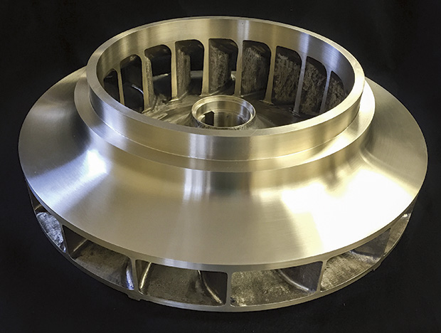
Image 1. New bronze impeller casting (Images and graphics courtesy of Hydro Inc.)
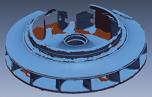
Figure 1. Reverse engineering raw scan data
Emergency equipment repairs are common throughout the industry. Having fewer spare parts makes this classification of repair more challenging. Standard equipment repairs typically take six to eight weeks, while emergency repairs must be completed within one day to three weeks, depending on the severity of the situation.
This type of repair often drives the need for rapidly supplied cast parts, which traditionally require long lead times because of the use of wooden tooling to create the mold to manufacture the casting.
Recent advancements in 3-D technology, known as additive manufacturing, allow the cast parts manufacturer to meet customer demands by eliminating the need to create traditional tooling.
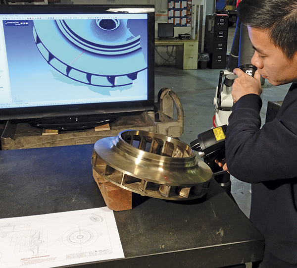
Image 2. An engineer verifies casting geometry to hydraulic design specifications.
While most users are familiar with subtractive manufacturing (the process of starting with a piece of metal and removing chips to produce the desired shape), additive manufacturing starts with a parametric model and ends with the desired shape.
Many materials are used during this process, but the most interesting and appropriate for rapid casting manufacturing is sand. With sand, casting tooling (molds and cores) can be created virtually overnight. This allows users to eliminate the delay involved in making wooden tooling for castings. Using additive manufacturing, a computer-controlled process, companies can create cast parts faster and with improved geometric tolerances than they can with the traditional casting processes.
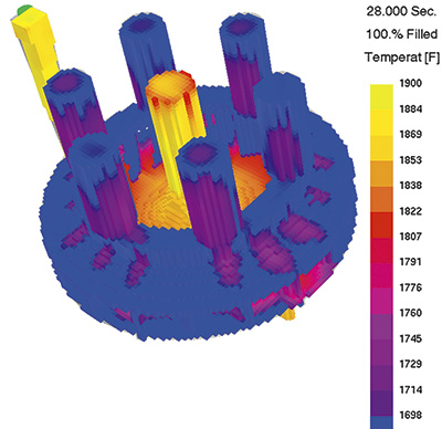
Figure 2. Temperature change during the pouring of casting
Once the geometry is defined, performing material solidification simulation of the casting is critical. The solidification software is designed around computational fluid dynamics, which allows engineers to simulate the velocities and temperature gradients of the metal throughout the pour cycle.
In the past, performing such analysis on every cast part was not common. Foundries typically had several experienced individuals who developed their casting pouring methods based on past experience.
With advancements in both software and equipment technology, engineers are now able to analyze the casting method design in more detail than ever before. Engineers can consider each casting with minimal delay in manufacturing. This is critical for pump parts, because most vane passage and volute areas have variable section thicknesses that can result in variable shrinkage. Variable shrinkage has been a problem in the foundry industry for many years. Institutes have developed casting tolerances to manage such variance. Technology is now allowing the industry to minimize the variance, which helps deliver castings within the design parameters set by hydraulic engineers.
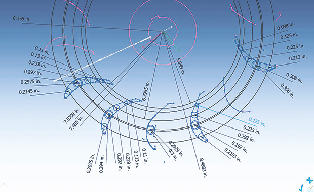
Figure 3. Vane hydraulic analysis
To meet vane dimensional accuracy, the challenge is to predict and control shrinkage inside the mold. During the manufacturing of a casting, three types of shrinkage can occur: shrinkage of the liquid, solidification shrinkage and patternmaker’s shrinkage. The problem of the shrinkage of the liquid can be ignored, since liquid metal is continuously supplied into the mold. The solidification shrinkage, which occurs because metals are less dense as a liquid than a solid, can be addressed with directional solidification design.
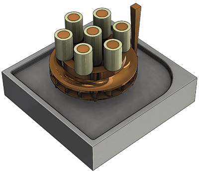
Figure 4. An image of drag mold with casting
This approach has enabled the company to correct and predict the effect of variable shrinkage in impellers while improving hydraulic accuracy of the impeller and obtaining better-than-standard casting tolerances on the vane passages. As a bonus to better hydraulic accuracy, this approach achieves a reduction in dynamic balancing costs as well as an improvement in the consistency of pump performance tests.
– See more at: http://www.pumpsandsystems.com/pumps/march-2015-new-3-d-casting-methods-produce-spare-parts-faster?page=2#sthash.0EJEF9eJ.dpuf