Close Inspection Solves High Thrust Bearing Temperature Problem

Careful analysis identified the issue with this multistage, oil transfer pump.

Written by: Gary Dyson (Hydro, Inc.)
Publisher: Pumps & Systems / August 2014


A multistage BB5 diffuser machine in oil transfer service in the Middle East had been in operation for many years without problems. After a routine maintenance strip down and rebuild, the pump experienced a high thrust bearing temperature of 105 C, which caused it to alarm and shut down. The temperature range had previously been 75 C to 85 C.

This case study describes the method used to solve the high bearing temperature problem and outlines the flow physics that contributed to the high thrust bearing temperature. The customer contacted an engineering services company after the original pump manufacturer failed to remedy the problem.

The company’s forensic approach to this problem involved two distinct methodologies:

  • Diligent and in-depth analysis of site data relating to 
the problem
  • Rigorous scrutiny and analysis of the pump geometry and build against the background

The engineering services company identified several scenarios that could cause this temperature rise, then narrowed down the list to establish a root cause.

Site Data Analysis

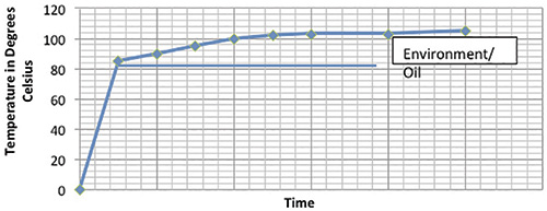
The behavior of thrust bearing pads during startup is seldom investigated. The temperature rise of the pads can be attributed to two distinct causes—thrust developed during startup and environmental and oil conditions (see Figure 1).

thrust-bearing-pad-behavior

Figure 1. Behavior of thrust bearing pads based on thrust and environmental conditions (Article images and graphics courtesy of Hydro Inc.)

The significant finding from this data was the temperature rise associated with thrust. The pump could not achieve the temperatures measured prior to maintenance in its current condition. The total thrust bearing temperature includes the oil temperature and environmental conditions.

Based on comparisons with previous site data, both the thrust and oil cooling had altered. Analysis of the temperature data at the motor bearings, which were experiencing oil temperature increases of 10 to 15 C, further supported the conclusion. Continue reading

Optimize High-Energy Pumps With Improved Impeller Design

As new design and manufacturing technologies are developed, end users can affordably upgrade their systems and verify better performance.

Written by: Bob Jennings & Dr. Gary Dyson (Hydro, Inc.)
Publisher: Pumps & Systems / August 2015


The rising cost of electrical power has caused many industrial plants to shift their focus to energy consumption. Plants often run pumping equipment continuously, and much research has pointed to opportunities for cost savings by optimizing pumping equipment.

When evaluating the potential for energy savings, end users cannot consider a pump in isolation. The suitability of the pump for the system within which it operates is vital. Even the best designed and most efficient equipment offers power-saving potential if it is run off its best efficiency point (BEP) in a system for which it is ill-applied.

test_orig

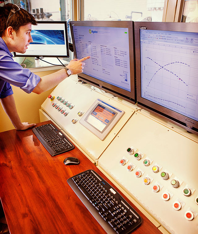
Image 1. Much research has pointed to opportunities for cost savings by optimizing pumping equipment. (Images and graphics courtesy of Hydro, Inc.)

Many plants have been in operation for more than 40 years, and their operating philosophies have changed over time. Plant improvements have enabled higher throughput, often increasing production by as much as 125-150 percent. Unfortunately, little is done to improve or increase the performance of the support-service pumping equipment, such as cooling water pumps.

As system flow demands increase, the duty point of the pumps is forced to shift far to the right of the BEP, well outside the acceptable operating range (AOR). This causes efficiency and pump reliability to decrease dramatically.

Casting tolerances, surface finishes, and impeller/volute or impeller/diffuser geometry have all dramatically improved during the last 40 years. But because many pumps were installed when the plants were commissioned, the existing pumps were manufactured using techniques that would be considered obsolete today. The result is higher energy costs and reduced reliability and availability, which often cause production delays. Continue reading

10 Key Facts About Reciprocating Pumps

This pump type’s unique system design requirements are often ignored or misapplied, which affects reliability and operation.

Written by: Gary Dyson and Herb Tackett Jr. (Hydro, Inc.)
Publisher: Pumps & Systems / July 2015


Because Centrifugal pumps are widely used, pump and rotating equipment engineers are generally familiar with this equipment’s operating principles, performance curves and selection criteria.


hydro-image-1

Image 1. While centrifugal pumps are the subject of much training, the dwindling population of reciprocating pumps has led to a loss of understanding of this pump type’s unique system design requirements. (Images and graphics courtesy of Hydro, Inc.)


While Centrifugal pumps are the subject of much training, the dwindling population of reciprocating pumps has led to a loss of understanding of this pump type’s unique system design requirements. Centrifugal pump specifications are now commonly and incorrectly applied to reciprocating pumps, which can lead to significant reliability problems.

End users should consider these 10 key facts about reciprocating pumps that can influence reliability and operation. Continue reading

New 3-D Casting Methods Produce Spare Parts Faster

Additive manufacturing also improves geometric tolerances.

Written by: Jesse Stinson (Hydro Parts Solutions) & Werner Barnard (Hydro Inc.)
Publisher: Pumps & Systems / March 2, 2015


An increasing number of industrial plants are reducing the spare parts inventories stored at their facilities. At the same time, they are replacing fewer pumps because of capital constraints and have determined that remanufacturing existing equipment is the best path forward. Many of the pumps within these facilities have exceeded 50 years of service. This drives the need for replacement parts and, in some cases, emergency replacement parts. Considering the age of these pumps, the replacement parts from the manufacturer are likely obsolete and may not be easily available. Further complicating the situation is the location of manufacture. Many cast parts are manufactured outside the U.S and have long lead times.

To address these challenges, many companies are developing technologies to meet the specific and growing demands of the industry. Many of these advanced tools, including coordinate measure machine (CMM) technology, allow for quicker emergency repairs, faster deliveries and higher quality pump parts.

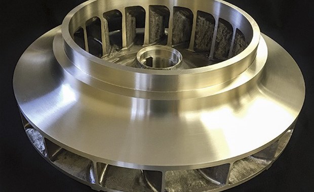
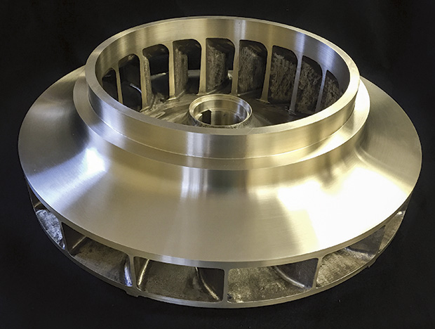
Image 1. New bronze impeller casting (Images and graphics courtesy of Hydro Inc.)

Image 1. New bronze impeller casting (Images and graphics courtesy of Hydro Inc.)

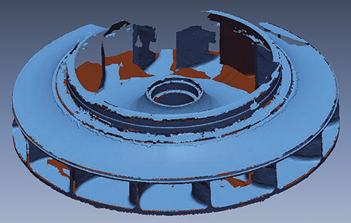
Figure 1. Reverse engineering raw scan data

Figure 1. Reverse engineering raw scan data

Emergency equipment repairs are common throughout the industry. Having fewer spare parts makes this classification of repair more challenging. Standard equipment repairs typically take six to eight weeks, while emergency repairs must be completed within one day to three weeks, depending on the severity of the situation.

This type of repair often drives the need for rapidly supplied cast parts, which traditionally require long lead times because of the use of wooden tooling to create the mold to manufacture the casting.

Recent advancements in 3-D technology, known as additive manufacturing, allow the cast parts manufacturer to meet customer demands by eliminating the need to create traditional tooling.

Continue reading

Eraring Power Station – NSW, Australia

Vertical Condensate Extraction Pump Upgrade

Written by: Greg James, Hydro Australia
Publisher: Pumps & Systems / October 2014


Station History
Eraring Power Station, located in the coal belt area at Lake Macquarie on the central coast of New South Wales, began generating in 1982, with all four units commissioned between 1982 and 1984. Formerly state owned under the banner of Eraring Energy until mid 2013, the station is now owned by Origin Energy, one of Australia’s largest electricity generators and retailers.

The power station underwent a significant upgrade during 2010 to 2012, increasing the output of all four generating units from 660MW to 720MW each. Eraring is the largest generating unit in the Origin group and has established itself as Australia’s largest power station since the upgrade.

Condensate Extraction Pumps
The pumps are the standard arrangement of condensate extraction pump used in the power generation industry: underfloor, vertically mounted, canned design, 4 stages with a double suction impeller and inline suction and discharge ports. Each of the four generating units has two 100% duty pumps, driven by a 1850kW 4 pole, electric motor.

Problems
For more than a few years, the life of the thrust bearing has been subjected to scrutiny after causing numerous premature failures and constant concern for the Station Operators, Maintenance Engineers and Management. The thrust bearing design was typical for the period that the pumps were manufactured, tapered back to back roller design incorporating both thrust and radial loads and the drive coupling configuration as part of the bearing cartridge.

Station Engineers had been researching the upgrade design options for a period of time, calling on the original equipment manufacturer, aftermarket service centres and bearing manufacturers for input and options to overcome this troublesome plant and work towards the best possible solution.

Contract Overview
In 2012, Eraring Energy released a tender for the upgrade project to several service providers. The project included a sizeable work scope including design and supply of a new white metal bearing cartridge with an appropriate pedestal and several other new components.

The contract specifications require maintaining the same pump drive couplings, electric motor, mechanical seal cartridge and as many of the original pump components, meaning there was substantial engineering work required by the Hydro Australia Engineers.

Contract Award
A contract of this size was sought after by several original equipment manufacturers and Hydro Australia Pty. Ltd. located in the Gippsland region at Morwell Victoria was awarded the contract late in 2012. The contract runs for a period of 4 years with the first pump installation completed in April 2013 and the final pump due for installation in 2016.

2014_10_22

Additional Requirements & Spare Pump
With the knowledge and experience of Hydro Australia with the supply of engineered spare parts, a major undertaking was to supply and a complete new discharge head, a first for Hydro Australia. The 2.5 m high and 1.7 m wide discharge head is the most significant component of the pump as it ties everything together. Other new components were manufactured by Hydro Australia including impellers, stage cases, wear rings, couplings and shafts. The new components complete with the stations spare parts, enabled a complete spare pump to be manufactured. This spare pump gives flexibility and relieves time critical exchanges and on the run maintenance. Continue reading