
-

Photo provided by BP of four IR 24 HV bottom-suction pumps and one IR 24 FV pump (P-15) in BP Whiting Refinery’s water station on Lake Michigan
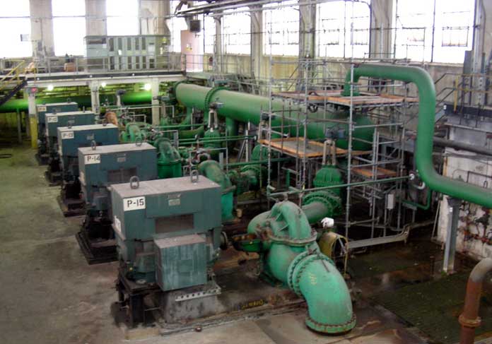
Positioned on the shores of Lake Michigan are two stations that contain cooling water pumps which feed cooling water to BP’s Whiting Refinery. The #1 water station contains four IR 24 HV pumps, which are large, single-stage, double-suction, horizontal split case pumps. Four pumps in station #1 (P-11, P-12, P-13, and P-14 in the photo below) are unique in that they were designed with a bottom-suction configuration.
-
Photo provided by BP of Cameron performance curve circa 1933
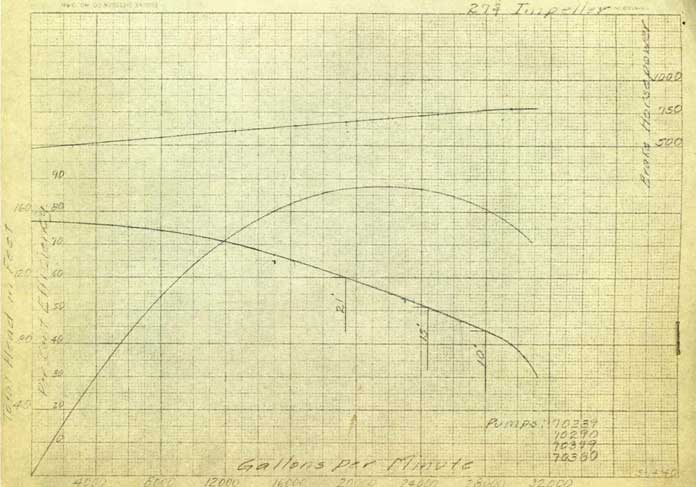
The rotating equipment engineers at the refinery wanted to better understand the operating characteristics of these pumps, which were originally built by Cameron in 1928. Because these pumps were installed so long ago, there was no NPSH data available and the pumps’ best efficiency point was not known.
BP’s rotating equipment engineers contacted Hydro, a reliable pump service provider with whom they had a long and positive relationship. Their initial inquiry for a pump performance test led to a review of the pumps’ operating environment. Hydro’s engineers learned that one pump was a designated spare and three of the four pumps were being run at a much lower capacity. Block valves had been used to limit the discharge pressure for the three operating pumps in an effort to prevent leaks in the cooling water piping inside the refinery.
Hydro’s engineers agreed with the refinery’s rotating equipment engineers that it would be beneficial to obtain the pumps’ best efficiency point. Running the pumps too far back on their operating curves could create internal forces that would be harmful to the pumps and decrease their operating life. For this reason, the refinery decided to pull one of the bottom-suction pumps from service to be tested. However, before sending this pump to Hydro’s independent test lab in Chicago, they seized the opportunity to make modifications that would enable the vintage pump to meet current standards.
The pump was promptly sent to Hydro and a comprehensive engineering analysis was performed. Hydro’s engineers communicated with the refinery’s rotating equipment engineers to determine the modifications and upgrades that could be made.
Engineered Modifications and Upgrades for an IR 24 HV Cooling Water Pump
The refinery’s rotating equipment engineers first asked Hydro’s engineers about redesigning the bearing housings. The original bearing housings were 2.5 foot long with spherical shell journal bearings that were hard to machine and made proper alignment difficult. More importantly, redesigning the bearing housings would help to reduce the weight on the external bearings. Because the bearings were identified to be an obsolete design, Hydro’s engineers evaluated new bearing configurations at the request of the refinery. Axial thrust and bearing loads were reviewed to determine the best bearing design. Modifying the bearing design gave the refinery another option to upgrade from packing to mechanical seals, which would provide an added benefit of reducing leakage and decreasing energy consumption. The evaluation of upgrading to mechanical seals prompted a review of shaft deflection, or bend in the shaft. Mechanical seals can accommodate a limited amount of shaft deflection, so the shaft would need to be redesigned to work with the mechanical seals.
-

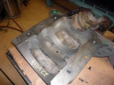
Photo above, courtesy of BP, shows original bearing housing.
-

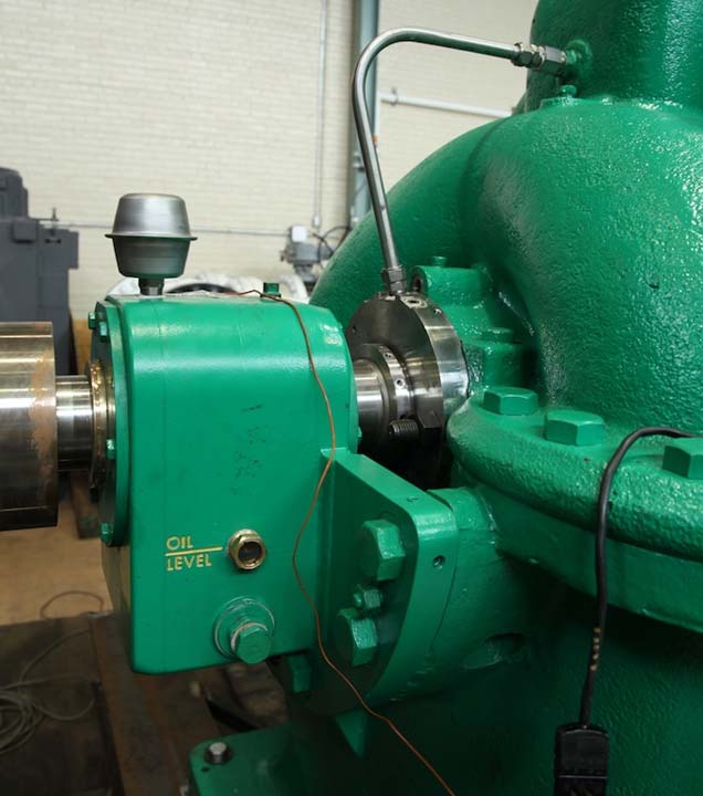
Photo provided by Hydro of new bearing housing, bearing and mechanical seal
Once the engineering review was complete and all the modifications were agreed upon, Hydro went to work. The shaft was modified to a stepped design and the distance between the bearings was shortened to reduce deflection at the seal faces. The sleeve bearings were removed and ball bearings were put in to greatly handle the axial thrust of the rotor, thus stabilizing the shaft and lowering vibration. New mechanical seals were installed along with newly manufactured bearing housings, which were fabricated at Hydro’s service center. Hydro manufactured the new bearing housings from steel plate using their 5-axis CNC machine.
Design changes were made to the impeller wear rings after a mechanical and metallurgical review was performed on the original cast iron wear rings. Hydro manufactured new impeller wear rings from a more durable stainless steel. The size of one impeller wear ring was made larger to reduce axial shuttling by prescribing the direction of axial thrust away from the thrust bearing. Specialized processes were used to machine, grind and metalize the impeller wear rings. The applied metal is harder than the parent metal, increasing the erosion resistance and extending the life span of the wear rings.
The pump casing was line-bored. Damage to the inside of the casing, which had been caused by axial shuttling and erosion, was repaired. The casing was also machined to create a larger bore for the new mechanical seal glands. After the pump rebuild was complete, the pump was shipped to the Hydro’s pump performance test lab in Chicago.
Testing an 800 Horsepower Bottom-Suction Pump
As the workscope of this project evolved, the purpose of pump testing grew to encompass additional goals for the refinery. The refinery wanted to:
Generate a performance curve to
- understand hydraulic performance and validate the modifications and upgrades made
- learn the pump’s best efficiency point
- understand at what operating points cavitation and recirculation could occur; thus helping to avoid those issues in the future
- determine if one pump could operate at a higher capacity in place of three pumps at reduced capacity
Perform an NPSH test to
- discover the pump’s suction characteristics
- measure the minimum suction pressure needed at each flow point to maintain stable pressure
- learn where the water elevation needed to be in water station #1
-

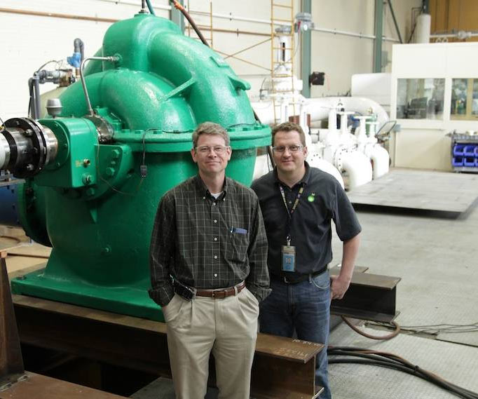
Photo provided by Hydro of Bill Rademacher and Jarrod Streets, BP’s Rotating Equipment Engineers, standing near IR 24 HV pump on test stand
To test the pump, Hydro’s Test Lab engineers designed and constructed a customized test configuration. Instead of placing this pump on the horizontal test stand, it was set up over the test lab’s vertical pit to accommodate the 30” bottom suction inlet. A sturdy baseplate was erected to support the 800-horsepower motor and the pump, which sat above the vertical pool that contained approximately 65,000 gallons of water. Attached to the pump’s suction inlet was a 17-foot column pipe that extended down into the pit and would be used to draw water up into the pump.
When a horizontal pump is tested, it is critical to flood the system before the pump is started. In actual operation in the field, the elevation of the water in the sump below the pumps is controlled by a sluice gate that holds back the water in Lake Michigan from flooding the water station. In this unique set up, all the water was well below the pump level; so Hydro’s test lab engineers had to back fill the pump using water from the 38,000 gallon tank on the horizontal test loop. A butterfly valve had been strategically affixed to the bottom of the column pipe and remained closed while Hydro’s test lab engineers opened the tank valve and flooded the pump. Once the pump was completely flooded, Hydro’s test lab engineers closed the valve to the tank and opened the butterfly valve to the pit. Using an eductor, a vacuum was created to keep the water from draining into the pit. This allowed for optimal pump start up conditions.
Test Results
-

Pump Performance Curve provided by Hydro Performance Test Lab Inc., Chicago IL
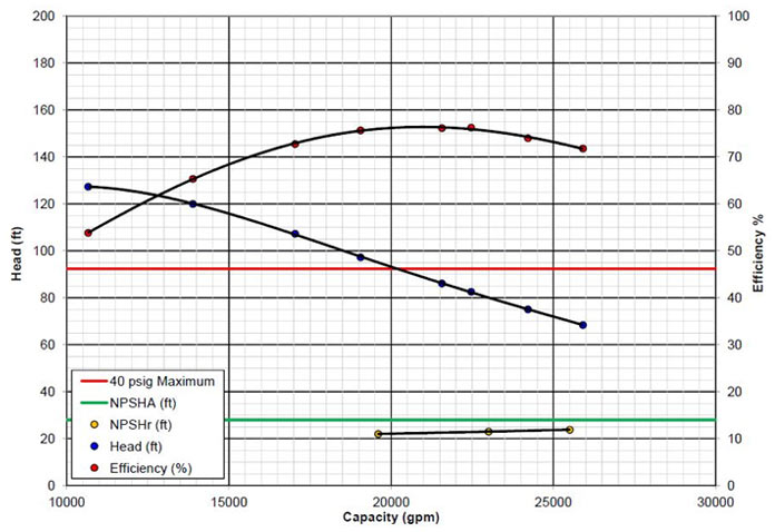
The tests showed that the pump can be operated to the right of BEP and still stay within net positive suction head available (NPSHa). The data indicates that one pump operating at a higher capacity can eliminate the need for three pumps operating at reduced capacity. These findings suggest significant potential energy savings for the refinery and may enable BP Whiting to run just one of these pumps in each water station during the winter months and two pumps in each water station during the summer months. “The performance testing we did went a long way toward allowing us to shut down unnecessary water pumps, and the modifications we made to this pump will allow us to run it more reliably,” confirms Bill Rademacher, one of the Rotating Equipment Engineers who helped lead the project.
Lessons Learned
Many pumps operating today were designed and manufactured several decades ago. When renewing a vintage pump, it is critical to work with a service provider who has a highly experienced engineering team that can perform a thorough review. If an upgrade is suggested, an in-depth engineering analysis will determine how that modification can affect the entire pump and pumping system. In this case, for example, the suggestion of one modification required other factors to be considered and led to a complete review of pump hydraulics, mechanical and metallurgical conditions. The BP Whiting refinery engaged Hydro, a service provider with a solutions-driven engineering team that took the time to review the pump’s operating conditions and original design specifications to make recommendations for improving the pump’s performance and extending its life.